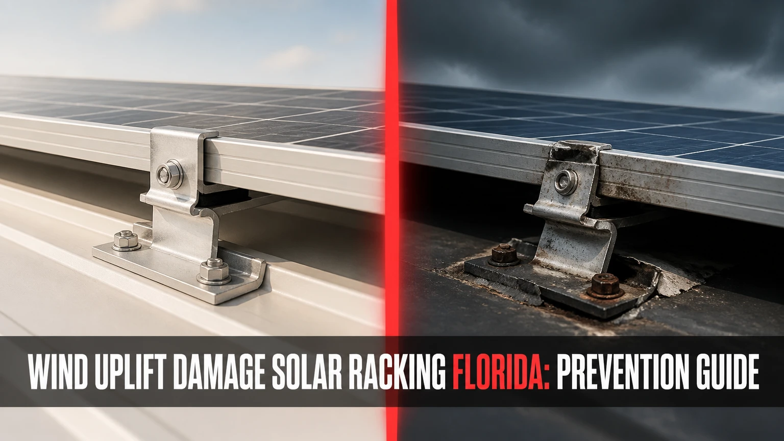
Wind uplift damage to solar racking in Florida occurs when hurricane wind creates suction above and pressure below an array, transferring force through panels, clamps, rails, fasteners, roof framing, and the building structure. Preventing collapse requires a site-specific design under the Florida Building Code, correct roof-zone pressures, verified structural attachments, and post-storm inspection by qualified professionals.
Key Facts at a Glance
Wind pressure increases with the square of wind speed, so a 10% speed increase produces approximately 21% more pressure.
Roof edges and corners receive higher local suction than interior roof areas, but the exact pressure depends on building geometry and the adopted design method.
Florida design wind speed is site-specific and must be selected from the applicable code wind-speed map, risk category, exposure, height, and enclosure classification.
A lag bolt is only as strong as its actual connection to the required rafter, truss, blocking, or structural deck.
Ballasted systems avoid roof penetrations but transfer substantial dead load and still require engineered wind calculations.
A visibly shifted array, torn flashing, exposed fastener, bent rail, cracked module, or new roof leak requires electrical isolation and professional assessment.
What Is Wind Uplift Damage Solar Racking Florida?
Wind uplift damage is structural damage caused by upward aerodynamic force on a photovoltaic array and its attachment system. Florida solar arrays experience uplift when fast wind accelerates over panel surfaces, separates near roof edges, and creates changing pressure that pulls modules, clamps, rails, and anchors away from the roof.
The load path matters more than the panel alone. Wind acts on the module, the module transfers force into clamps, clamps load the rail or mounting foot, and the mounting foot transfers tension and shear into fasteners, framing, the deck, or ballast. Failure at any link can release neighboring connections.
A panel can remain visually intact while its attachment is already compromised. That is why a post-hurricane inspection must examine fastener withdrawal, rail deformation, flashing, roof membranes, module frames, and electrical components rather than relying on a ground-level glance.
Why does wind pull panels upward?
Wind moving across a tilted or elevated panel array creates a pressure difference between the exposed upper surface and the lower surface. Flow separation, turbulence, roof-edge vortices, and panel tilt can increase net uplift, while wind parallel to a roof can produce different forces from wind approaching the array broadside.
The Bernoulli effect helps explain pressure differences, but it is not a complete solar-racking design method. Engineers also account for external pressure coefficients, internal building pressure, gust effects, roof zones, shielding, parapets, array spacing, panel tilt, and connection behavior.
Wind pressure is commonly represented in simplified form as:
q = 0.00256KzKztKdV²
The exact equation and coefficients depend on the adopted standard and design case. The practical point is stable: velocity is squared. At 120 mph, a simplified velocity-squared term is 14,400; at 132 mph, it is 17,424, an increase of 21%.
How Does Failure Progress During a Florida Hurricane?
Solar racking failure often begins with excessive local movement and ends with connection withdrawal, rail release, module breakage, or roof-deck damage. The sequence is not inevitable, because a properly designed array may remain within its elastic range, but weak connections can turn one failed attachment into a larger progressive failure.
1. Wind reaches the roof edge
The first panel row near an exposed roof edge can encounter separated flow and turbulent vortices. Corners are especially sensitive because wind can approach from two roof directions, increasing local suction and changing the load direction.
2. Modules and rails flex
Repeated gusts create cyclic tension, compression, and shear. Aluminum rails bend within their limits when correctly supported, but excessive spans, missing fasteners, loose clamps, or incompatible components allow larger movement.
3. Connections lose capacity
A split rafter, undersized lag, stripped thread, corroded bolt, crushed deck, or poorly seated clamp can reduce resistance. Fatigue is less visible than a snapped component, so torque records and attachment photographs have high diagnostic value.
4. A connection pulls out
When one attachment yields, adjacent fasteners receive redistributed force. The array may then tear through flashing, membrane, roof deck, or framing. A “zipper” pattern is a field description of progressive connection failure, not a guaranteed failure mode for every array.
| Failure location | Visible symptom | Likely structural concern | Immediate action |
|---|---|---|---|
| Module clamp | Module movement, frame marks, exposed clamp edge | Clamp slip or incorrect torque | Keep clear and isolate system |
| Aluminum rail | Bowing, twist, displaced rail | Excessive span or fastener movement | Photograph without touching |
| Roof attachment | Lifted flashing, torn sealant, exposed lag | Withdrawal, split framing, water entry | Stop roof access |
| Ballast tray | Shifted blocks, displaced deflectors | Sliding, overturning, inadequate ballast | Restrict roof access |
| Module | Cracked glass, bent frame, hot spot | Mechanical and electrical damage | Have electrician assess |
Which Florida Rules Govern Solar Racking Wind Resistance?
Florida solar-racking design is governed by the locally adopted Florida Building Code, the referenced structural standard, local permitting requirements, and product-specific engineering. The applicable design is not determined by a statewide single wind number, because county, municipality, site exposure, building height, risk category, enclosure, roof geometry, and HVHZ status affect the calculation.
The Florida Building Code 8th Edition, 2023, became effective on December 31, 2023. Its structural provisions reference current standards and local amendments. Miami-Dade and Broward County properties in the High-Velocity Hurricane Zone also face additional requirements, including product approval and high-wind detailing that may not apply elsewhere in Florida.
The code’s governing principle is direct: “Buildings and structures, and all parts thereof, shall be designed and constructed to resist…” the applicable loads, including wind, as stated in the Florida Building Code. The building official, design professional, and permit documents determine the enforceable application.
What design inputs must an engineer verify?
A wind calculation should identify the project address, applicable wind-speed map, risk category, exposure category, mean roof height, roof angle, parapets, surrounding obstructions, enclosure classification, panel tilt, array geometry, roof zones, and attachment spacing. It should also identify positive pressure, negative pressure, uplift, lateral shear, and load combinations.
A product datasheet alone does not prove that a complete array is adequate. The engineer must connect the manufacturer’s allowable or tested capacity to the actual roof substrate and installation pattern.
| Design input | Typical range or classification | Why it changes the result | Required evidence |
|---|---|---|---|
| Ultimate wind speed | About 110-180+ mph by site | Velocity is squared in pressure calculations | Code map or approved software |
| Roof exposure | Exposure B, C, or D | Open terrain increases wind effects | Site and surrounding-terrain review |
| Roof height | Residential low-rise to high-rise | Height changes velocity pressure | Architectural plans or field measure |
| Risk category | Commonly II, sometimes III or IV | Importance affects design criteria | Building classification |
| Roof zone | Interior, edge, corner | Local suction varies by location | Array layout with dimensions |
| Attachment substrate | Rafter, truss, structural deck, concrete | Pullout and shear capacity differ | Framing plans or verification |
Are Florida wind pressures always 50-150 psf?
No universal 50-150 psf uplift range applies to every Florida solar array. Local component and cladding pressures can reach high values in exposed roof zones, particularly in HVHZ locations, but the correct value depends on the code method, tributary area, coefficients, load combination, and array geometry.
A quoted pressure without its zone, effective wind area, sign convention, and design standard is incomplete. Ask for the calculation page that identifies net uplift pressure and the resulting force at each attachment.
Why Do Roof Edges and Corners Matter?
Roof edges and corners generally receive greater wind suction than interior roof areas because airflow separates at discontinuities and forms concentrated vortices. Solar modules installed near eaves, ridges, gable ends, and corners therefore require a layout-specific analysis rather than a simple uniform attachment pattern.
The common “Zone 1, Zone 2, Zone 3” diagram is useful for communication, but zone dimensions and pressure coefficients are not universal. ASCE 7 provisions, Florida amendments, building shape, roof height, parapets, and effective wind area determine the design zones.
A three-foot setback can be a practical layout choice on some residential roofs, but it is not a blanket code exemption. An array that fits inside an interior-looking area may still cross a calculated edge zone if the roof is small or irregular.
Which Racking System Is Best for Florida Wind?
Rafter-connected flush rail racking is usually the most broadly adaptable choice for residential pitched roofs, provided fasteners reach verified framing and the system has project-appropriate engineering. No racking type is automatically hurricane-proof: performance depends on the complete load path, roof condition, layout, connection spacing, and installation quality.
| Racking system | Typical planning cost | Wind-resistance advantage | Main limitation |
|---|---|---|---|
| Flush rail, pitched roof | $0.10-$0.18/W hardware | Low profile and distributed framing attachments | Requires roof penetrations |
| Rail-less direct mount | $0.08-$0.14/W hardware | Fewer continuous rails and compact layout | High sensitivity to missed framing |
| Ballasted flat roof | $0.15-$0.25/W hardware | Avoids most penetrations | Adds dead load and sliding risk |
| Bonded commercial mount | $0.20-$0.32/W hardware | Limits penetrations on approved membranes | Adhesion depends on substrate and preparation |
| Ground mount or tracker | $0.25-$0.45/W hardware and structure | Independent foundation and storm stow options | Requires geotechnical and civil work |
Costs are typical planning ranges, not bids. They exclude engineering, permitting, reroofing, electrical work, cranes, taxes, roof repairs, and difficult access.
Flush-mounted rail systems
Flush rail systems attach aluminum rails to roof framing through flashed or engineered mounts. Their low profile reduces exposed projected area compared with steeply tilted rooftop arrays, while rails can distribute module reactions across several framing points.
The principal failure risk is a wrong attachment. A lag installed only into sheathing or plywood does not have the same withdrawal capacity as a fastener embedded in a verified rafter or truss. Tile roofs add a separate risk because cracked tiles and poorly supported replacement tiles can admit water even when the structural connection survives.
Ballasted systems
Ballasted systems use trays, blocks, pavers, or proprietary ballast assemblies to resist uplift without routine roof penetrations. They can work on Florida commercial roofs only when the roof structure, membrane, parapets, wind zones, sliding resistance, and ballast layout are engineered together.
Ballast is not a shortcut around wind design. A system may require heavier perimeter ballast, mechanical restraints, wind deflectors, or a hybrid attachment pattern. Older roofs may not support the additional dead load, and displaced blocks can damage membranes or rooftop equipment.
Bonded systems
Bonded mounts use an adhesive or manufacturer-approved attachment method on a compatible roof membrane or surface. They are useful where penetrations are undesirable, but bond performance depends on substrate condition, preparation, temperature, humidity, cure time, aging, and approved installation details.
Bonded systems are not appropriate for every shingle roof, contaminated membrane, wet surface, deteriorated roof, or unverified adhesive combination. A product approval or test report applies only within its stated roof assembly and installation limits.
Ground-mounted and tracker systems
Ground-mounted arrays transfer wind forces through steel posts, helical piles, driven piles, or concrete foundations. Trackers can reduce aerodynamic exposure by moving to a manufacturer-defined storm position, but automatic stow is a risk-control feature, not a substitute for foundation design.
A tracker needs functioning controls, anemometers, communications, backup power, and a tested fail-safe position. A storm arriving after grid loss can expose weaknesses if the controller cannot complete stow.
What Installation Errors Cause Solar Rack Uplift?
The most damaging installation errors are missed structural members, incorrect fastener embedment, uniform attachment spacing across different roof zones, improper clamp torque, incompatible metals, and installation over an aging roof. These errors reduce the actual capacity of a system that may look compliant from the ground.
| Field error | Typical consequence | Detection method | Corrective path |
|---|---|---|---|
| Rafter miss | Low withdrawal resistance | Framing scan and selective verification | Add approved structural attachment |
| Short lag | Insufficient embedment | Fastener measurement and plans | Replace under engineering direction |
| Over-torqued clamp | Deformed module frame or rail | Torque audit and visual marks | Replace damaged hardware |
| Aluminum-steel contact | Galvanic corrosion | Corrosion inspection and material review | Isolate metals and replace affected parts |
| Edge-zone uniformity | Underdesigned perimeter forces | Compare layout with calculations | Redesign spacing or array boundary |
| Roof deterioration | Deck or membrane failure | Roof core, attic, or membrane inspection | Repair or reroof before solar work |
A calibrated torque wrench matters, but torque does not verify pullout capacity. Torque indicates installation tightness; framing type, embedment, fastener diameter, edge distance, corrosion, and substrate determine structural resistance.
Salt exposure accelerates corrosion, particularly near coastal environments. Stainless steel, hot-dip galvanized steel, aluminum, sealants, washers, and flashing must be selected as a compatible assembly rather than mixed casually in the field.
How Should You Inspect Wind Uplift Damage After a Storm?
A safe post-storm inspection starts from the ground and stops before anyone climbs onto a wet, damaged, or electrically unsafe roof. The owner should photograph the array, check for obvious displacement and leaks, contact the installer and insurer, and use a qualified solar electrician and structural professional for energized or structural assessment.
Owner screening
Look for shifted rows, uneven module planes, broken glass, detached wires, hanging conduit, missing trim, lifted flashing, new ceiling stains, bent rails, displaced ballast, and debris impact. Do not touch cracked modules, exposed conductors, loose rails, or wet electrical equipment.
Turn off the system only according to the manufacturer’s emergency procedure and only when the disconnect is accessible and safe. Photovoltaic modules can produce voltage in daylight even when the inverter is off.
Professional assessment
A qualified inspector should compare the as-built array with approved plans, identify every damaged component, test representative attachments where appropriate, inspect roof framing or structural deck, check grounding and bonding, and document the result with photographs and measurements.
Thermal imaging can help find electrical abnormalities, but it does not prove that a lag has adequate pullout resistance. Adhesive installations require the manufacturer’s specified inspection or test method, not an improvised luggage scale. Field tests must avoid damaging a membrane or invalidating a warranty.
| Inspection finding | Risk level | Do not do | Appropriate next step |
|---|---|---|---|
| Cosmetic dirt only | Low | Do not pressure-wash damaged modules | Routine service inspection |
| One cracked module | Moderate | Do not handle glass or connectors | Electrical and replacement assessment |
| Shifted rail or row | High | Do not straighten it by hand | Structural inspection and isolation |
| Torn flashing or membrane | High | Do not apply generic roof cement | Roofing repair coordinated with solar |
| Hanging conductor | High | Do not reconnect it | Qualified electrician and system shutdown |
| Multiple detached modules | Critical | Do not enter roof area | Secure perimeter and emergency assessment |
Can Damaged Solar Panels and Racking Be Repaired?
Repair is appropriate when damage is localized, the roof and load path remain sound, replacement components are available, and an engineer or qualified contractor confirms that the repaired array matches its approved design. Replacement is usually more appropriate when rails, framing connections, multiple modules, waterproofing, or the roof deck sustained widespread damage.
A cracked module is not equivalent to a shifted array. A module may require replacement for electrical safety while the racking remains usable, whereas a rail pulled from framing can require array removal, roof repair, structural reinforcement, new flashing, and permit revisions.
Insurance documentation should include the pre-storm array layout, invoices, permits, product information, serial numbers, photographs, weather date, inspection report, and repair estimate. Do not conceal damage with sealant or reinstall modules before documenting the condition.
When should an array be removed?
Remove or isolate an array when modules are detached, conductors are exposed, roof attachments have pulled out, ballast has shifted into unsafe positions, the roof deck is damaged, or water reaches electrical equipment. Emergency removal should preserve evidence and follow electrical, fall-protection, and roofing safety procedures.
How Much Does Hurricane-Ready Solar Racking Cost?
For planning, rooftop racking hardware commonly falls around $0.08-$0.32 per watt, while ground-mounted structural hardware often falls around $0.25-$0.45 per watt. Engineering, permits, roof reinforcement, reroofing, electrical repairs, specialty access, and post-storm removal can exceed the hardware cost.
| Project condition | Typical added cost | Typical duration | Main cost driver |
|---|---|---|---|
| Standard pitched-roof design | $500-$2,000 engineering and permit allowance | 1-3 weeks planning | Site review and permit package |
| Coastal or HVHZ design | $1,500-$5,000+ engineering allowance | 2-6 weeks planning | Product approval and detailed wind design |
| Commercial ballast review | $2,000-$10,000+ engineering allowance | 2-8 weeks planning | Structural and membrane coordination |
| Post-storm structural inspection | $500-$2,500 typical | 1-5 business days | Access, testing, and documentation |
| Array removal and reinstall | $0.30-$1.00/W typical labor range | 1-5 days | Module count, roof repairs, access |
These figures are not regulated fee schedules and vary by region, system size, damage extent, and permit complexity. A low installation price that omits structural engineering can create a much larger repair liability.
What Should Florida Property Owners Require?
Florida homeowners should require an approved layout, structural attachment details, roof-framing verification, product documentation, electrical permits, and closeout records. Commercial owners should also require roof warranty coordination, ballast calculations, maintenance access, corrosion specifications, and a plan for hurricane shutdown or inspection.
Ask the contractor for these documents before installation:
- Site-specific wind design criteria and applicable code edition.
- Array plan showing dimensions, roof edges, corners, setbacks, and attachment points.
- Structural calculations identifying uplift and lateral reactions.
- Fastener type, diameter, embedment, substrate, and corrosion protection.
- Manufacturer installation manual and approval or evaluation documentation.
- Roof condition report with remaining service-life estimate.
- Permit number, inspection status, and final approval records.
- Storm inspection and maintenance procedure.
A practitioner rule is worth remembering: never approve a solar attachment from a roof photograph alone when framing location is uncertain. Attic access, probing, imaging, or construction documents can prevent a rafter miss that remains hidden until the first major storm.
FAQ About Wind Uplift Damage Solar Racking Florida
Does a low-profile solar array eliminate hurricane uplift?
No. A flush-mounted array usually reduces projected area and overturning leverage compared with a steeply tilted array, but it still experiences roof-zone suction and lateral shear. Attachment location, roof geometry, edge distance, framing capacity, module spacing, and wind direction determine the final demand.
Can solar panels protect a Florida roof from wind?
Solar panels can sometimes shield portions of a roof from direct weathering, but they do not reliably protect roof membranes from hurricane uplift. Racking penetrations, flashing, ballast movement, and trapped debris create additional maintenance points, so the roof must be sound before the array is installed.
Is a Miami-Dade product approval enough for every Florida installation?
No. Product approval supports compliance for the approved assembly and conditions, but the project still needs correct site wind criteria, roof attachment, layout, substrate, installation, and local permitting. A Miami-Dade approval does not automatically validate an installation outside its listed scope.
How often should Florida solar racking be inspected?
Inspect the array after every severe tropical storm or hurricane and during routine roof maintenance. Coastal properties, commercial roofs, older arrays, and systems with visible corrosion benefit from documented annual inspections, while unusual movement or leaks justify immediate evaluation.
Does a battery change the wind-uplift design?
A battery usually does not change rooftop module uplift calculations, but it changes electrical, fire, equipment-clearance, structural, and flood-elevation requirements. Wall-mounted or ground-mounted battery equipment needs its own attachment and enclosure review, especially in coastal and flood-prone locations.
The Bottom Line
Wind uplift damage solar racking Florida projects is prevented through a verified load path, not through a panel brand or a generic hurricane rating. Require site-specific Florida Building Code calculations, correct roof-zone treatment, structural attachment verification, compatible corrosion-resistant hardware, and documented inspections after severe weather. If an array has shifted, pulled out, leaked, or exposed wiring, isolate the hazard and obtain structural and electrical assessments before repair or re-energization.