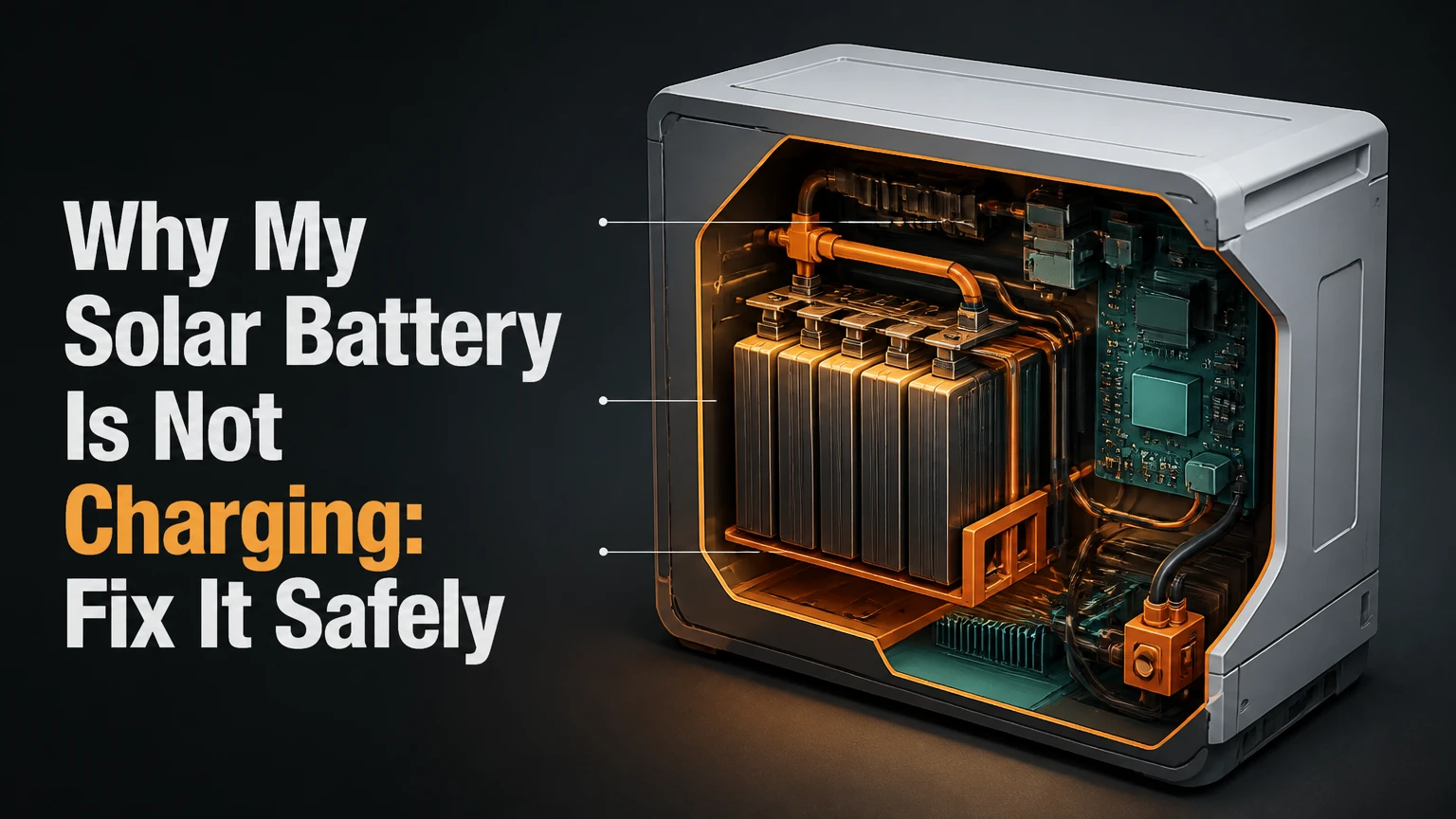
A solar battery is not charging because solar energy is being lost at one of three points: the panels are not producing enough DC power, the controller or inverter is not passing regulated power, or the battery management system is refusing energy for safety. The fastest diagnosis compares daytime panel power, charger status, battery voltage, temperature, settings, and error codes in that order.
Key Facts at a Glance
- A solar battery can show little or no charging current when household loads consume all available solar power.
- Lithium batteries commonly stop charging because their BMS detects low temperature, overvoltage, undervoltage, or a communication fault.
- A charge controller needs sufficient PV voltage above battery voltage, but the exact operating threshold depends on the controller model.
- A battery that reaches its configured full-charge voltage may correctly reduce current to nearly zero.
- Never bypass a lithium battery’s BMS or apply an unapproved “boost” charger to a deeply discharged battery.
- A blown fuse, open breaker, reversed cable, or loose terminal can interrupt charging even when the panels produce power.
Why does a solar battery stop charging?
A solar battery stops charging when generation, power conversion, wiring, battery protection, or battery chemistry prevents current from reaching and entering the cells. Diagnosis should begin with live measurements rather than the battery percentage shown in an app, because state-of-charge estimates can remain inaccurate after a shutdown, reset, or cell imbalance.
The complete path is:
Solar panels → PV isolator and cables → MPPT or PWM controller → DC fuse or breaker → battery terminals → BMS → cells
A fault anywhere in that chain produces similar symptoms. For example, a shaded panel string can leave the inverter online while providing too little voltage for the MPPT tracker, whereas a lithium BMS can block charging despite normal PV voltage and an apparently healthy battery.
What does normal charging look like?
Normal solar charging usually moves through bulk, absorption, and either float or standby behavior. During bulk charging, the controller supplies the highest available current until the battery approaches its charge-voltage target. During absorption, voltage remains controlled while current declines; lithium systems often finish charging quickly and then stop rather than maintain a lead-acid-style float voltage.
| Charging stage | Typical controller behavior | Lead-acid example | Lithium example |
|---|---|---|---|
| Bulk | Maximum available current | 14.2-14.8 V for a 12 V bank | 14.0-14.6 V for a 12 V LiFePO4 bank |
| Absorption | Constant voltage, falling current | 1-4 hours, model-dependent | Often 0-30 minutes, model-dependent |
| Float | Lower maintenance voltage | 13.2-13.8 V | Disabled or reduced by manufacturer |
| Standby | Charging pauses at high SoC | Current near 0 A | Current near 0 A |
The values are typical ranges, not universal settings. Use the battery manufacturer’s specifications, especially for sealed lead-acid, lithium iron phosphate, and high-voltage home batteries.
How does a solar battery charge?
Solar panels create variable DC voltage, an MPPT or PWM controller regulates that energy, and the battery’s BMS or internal protection circuit decides whether the cells may accept it. The controller can only charge when panel voltage, battery voltage, temperature, polarity, and programmed limits fall within the system’s operating range.
A practical diagnostic follows the energy path:
- Generation: sunlight produces panel voltage and current.
- Tracking: an MPPT controller selects an efficient panel operating point; a PWM controller pulls panel voltage closer to battery voltage.
- Regulation: the controller limits charging voltage and current.
- Protection: fuses, breakers, disconnects, and the BMS check for unsafe conditions.
- Storage: electrochemical reactions store energy in the battery cells.
A 400 W array does not necessarily deliver 400 W to storage. If the home is using 350 W at midday, only roughly 50 W remains for charging, before conversion losses. A battery app showing 0 W can therefore indicate load priority rather than equipment failure.
What should you check first?
Check the battery’s charge status, PV watts, error code, temperature, and visible disconnects before removing covers or testing live conductors. Record the readings at midday under clear conditions, because a nighttime reading cannot distinguish a fault from normal absence of solar input.
| Observation | Most likely cause | Safe first check | Escalation point |
|---|---|---|---|
| PV watts show 0 W in bright sun | PV isolator, breaker, cable, inverter fault, or severe shading | Check app status and labeled disconnects | Electrician if DC fault remains |
| PV watts are present, battery watts are 0 W | Full battery, charge limit, BMS block, or setting | Check SoC, temperature, and alarms | Battery installer if alarm persists |
| Battery voltage is low and controller says “sleep” | Deep discharge or BMS shutdown | Follow the battery manual’s wake procedure | Manufacturer or installer |
| Charging stops below 80% | Reserve setting, temperature limit, cell imbalance, or communication fault | Check maximum SoC and alarms | Qualified service provider |
| Charge starts then stops repeatedly | Loose connection, overtemperature, voltage limit, or failing battery | Inspect only accessible, de-energized terminals | Installer if cycling continues |
Step 1: Check whether the solar array is producing power
Confirm that the panels are producing measurable PV power before diagnosing the battery. Look for shading from chimneys, trees, satellite dishes, snow, leaves, and bird debris; one shaded module can reduce a series string substantially, although the exact effect depends on bypass diodes and array wiring.
Use the inverter or controller display to record PV voltage, PV current, and PV watts. A voltage reading alone does not prove useful generation, because an open-circuit array can show normal voltage while delivering almost no current through a failed fuse, connector, or controller input.
| System condition | Typical indication | Interpretation |
|---|---|---|
| Clear midday, 1 kW array | 500-900 W | Plausible output after heat, orientation, and losses |
| Heavy shading on one string | 10-40% of expected array power | Inspect module and string shading |
| PV voltage present, PV current 0 A | 0 W | Open circuit, failed input path, or controller issue |
| PV voltage below controller start range | Controller offline or no charge | Array configuration or low-light problem |
| PV output below household load | Battery power 0 W | Solar is serving loads first |
Do not assume the panel label voltage is the voltage available at the controller. Cable losses, cold-weather voltage limits, series-string faults, and isolator problems can change the measured value.
Step 2: Inspect inverter settings and error history
Verify that the inverter or charge controller recognizes the battery chemistry, nominal voltage, maximum charge current, minimum temperature, and permitted state-of-charge range. A lead-acid profile can apply unsuitable voltage to lithium, while an overly conservative lithium profile can stop charging well below the battery’s usable capacity.
Check these settings:
- Battery type: LiFePO4, NMC, AGM, gel, or flooded lead-acid.
- Maximum SoC: commonly 90-100%, depending on the manufacturer.
- Charge priority: solar loads first, battery first, or export first.
- Time-of-use schedule: scheduled charging may override daytime solar charging.
- Battery communication: CAN or RS485 link, if required.
- Firmware and alarm history: record the exact code and timestamp.
A restart can clear a software lock, but follow the equipment manual. A common sequence for some hybrid systems is to isolate PV, isolate battery, wait several minutes, restore the battery, then restore PV. Do not generalize that order to every brand.
Step 3: Test the charging path safely
Inspect accessible cables, connectors, fuses, and breakers for heat discoloration, corrosion, looseness, damaged insulation, or an open position. Turn off the relevant disconnects before tightening or removing any connection, and never disconnect a battery under load unless the manufacturer permits it.
A qualified person can measure voltage at successive points: PV input, controller output, battery-side fuse, and battery terminals. A large voltage difference between two points under charge indicates resistance in the cable, fuse, breaker, or termination.
| Charging-path point | Measurement to collect | Fault suggested by abnormal result |
|---|---|---|
| PV input terminals | Voltage, current, watts | Array, isolator, connector, or string fault |
| Controller output | Battery-side voltage and current | Controller, fuse, or output wiring fault |
| Battery-side fuse | Voltage on both sides under load | Open or high-resistance fuse connection |
| Battery terminals | Voltage during charge attempt | Cable drop, BMS block, or battery fault |
| Communication port | Link status and alarm | CAN, RS485, termination, or protocol mismatch |
Do not measure current by placing a multimeter across battery terminals. That creates a short circuit and can cause burns, fire, meter damage, or battery failure.
Step 4: Determine whether the battery is asleep or protected
A lithium battery may stop accepting charge after deep discharge because its BMS opens the charging and discharging circuits. The battery can appear electrically dead even when the cells are not irrecoverable, but the correct wake-up method depends on the manufacturer and model.
Check the battery display or app for undervoltage, low-temperature, overtemperature, overcurrent, cell imbalance, or communication alarms. If the battery manual specifies a wake button, approved charger, or minimum recovery voltage, follow that procedure exactly. Some batteries require a compatible inverter to send a wake command.
Never bypass the BMS, parallel a “dead” lithium battery directly with a full battery, or connect an automotive charger without confirming compatibility. A 12 V lithium battery at 10 V is not automatically safe to force-charge, and a 48 V battery pack requires equipment matched to its exact voltage and communication requirements.
Could cold temperature block solar charging?
Yes. Many LiFePO4 batteries block charging near 0°C or below, while the allowable discharge temperature is often lower. Charging cold lithium cells can cause lithium plating, so a BMS may correctly reduce current to zero until the cells warm above the permitted threshold.
| Battery chemistry | Typical charge range | Typical discharge range | Cold-weather implication |
|---|---|---|---|
| LiFePO4 | 0-45°C | -20-55°C | Charging may stop below 0°C |
| NMC lithium-ion | 0-45°C | -20-60°C | BMS temperature limits still apply |
| AGM | -20-50°C | -20-50°C | Capacity falls in cold conditions |
| Flooded lead-acid | -20-50°C | -20-50°C | Charging voltage compensation may be needed |
These ranges vary by product. Battery temperature, not outdoor air temperature alone, determines whether charging is permitted. A battery installed in an unheated garage can remain below its charging threshold hours after sunrise.
Does battery chemistry change the diagnosis?
Battery chemistry changes the likely failure mode, charging voltage, permissible depth of discharge, and response to cold conditions. LiFePO4 usually has high cycle life and usable capacity, whereas lead-acid batteries tolerate different charging practices but lose life rapidly when repeatedly discharged below recommended limits.
| Battery type | Typical cycle range | Usable DoD target | Typical round-trip efficiency | Main charging concern |
|---|---|---|---|---|
| LiFePO4 | 4,000-6,000 cycles | 80-100% | 90-98% | BMS, temperature, communication |
| NMC | 2,000-3,000 cycles | 80-90% | 90-95% | Temperature and thermal protection |
| AGM | 400-800 cycles | About 50% | 75-85% | Sulfation and incorrect absorption |
| Flooded lead-acid | 800-1,200 cycles | About 50% | 70-85% | Water level, sulfation, ventilation |
The cycle figures are typical industry ranges, not guarantees. Battery University explains that lead-acid batteries “should not be discharged beyond 50 percent,” because deeper cycling reduces service life, while lithium systems are designed around different operating limits.
Flooded batteries need electrolyte checks, distilled water, ventilation, and protection from hydrogen accumulation. AGM batteries are sealed but can still fail from sulfation, overcharging, age, or repeated deep discharge.
Could the battery already be full?
A full battery can correctly accept almost no current, especially in a lithium system configured to stop at 90% or 100% SoC. Confirm that PV power is being diverted to household loads or the grid, and check whether the battery voltage has reached its programmed charge limit.
A normal full-charge state usually has:
- High or configured maximum SoC.
- PV power available.
- Battery charge current near zero.
- No persistent battery alarm.
- Stable voltage after charging stops.
A battery that displays 100% but immediately collapses to a low SoC under a modest load may have lost capacity or developed cell imbalance. A battery that remains at 60-80% for hours with available PV requires closer investigation of settings, temperature, communication, and cell voltage.
Are household loads consuming all solar power?
A solar battery may not charge because the array is undersized for simultaneous loads. Calculate the net charging power:
Net battery input = solar generation – household demand – inverter and wiring losses
For example, a 3 kW array producing 2.1 kW while a home consumes 2.0 kW may deliver only about 0.1 kW, or 100 W, to the battery. Cloud movement can push that small surplus below the inverter’s minimum charging threshold.
Record PV production and load power at 15-minute intervals through a clear day. If the battery charges when the oven, heat pump, or electric vehicle is off, the battery is likely responding normally to the programmed energy-priority strategy.
When is battery replacement likely?
Replacement becomes likely when a battery fails capacity testing, repeatedly trips protection under normal loads, shows severe cell imbalance, leaks, swells, overheats, or cannot hold voltage after a complete manufacturer-approved charge. Age alone does not prove failure, but older lead-acid banks deserve particular suspicion after repeated deep discharge.
| Symptom | Likely service action | Typical timeframe | Typical cost range |
|---|---|---|---|
| Blown DC fuse | Replace with identical rated fuse after fault check | 30-90 minutes | $20-$150 |
| Loose or corroded terminal | De-energize, clean, torque, inspect cable | 30-120 minutes | $100-$300 |
| Controller configuration error | Correct profile and limits | 15-60 minutes | $0-$250 |
| Failed 12 V AGM battery | Replace matched battery bank | 1-3 hours | $150-$500 per battery |
| Failed LiFePO4 module | Diagnostic and module replacement | 2-6 hours | $400-$1,500 per module |
| Home storage battery replacement | Certified service and commissioning | 4-10 hours | $5,000-$15,000 installed, typical |
Costs vary by region, access, permits, warranty, battery voltage, and installer rates. High-voltage home storage systems require certified service; homeowners should not open battery enclosures.
What changes for RV, off-grid, and grid-tied systems?
RV systems most often require checks of portable-panel connections, roof glands, battery cutoffs, and DC fuses. Off-grid cabins require checks of overnight depth of discharge, generator integration, and whether winter loads exceed daily solar production. Grid-tied home systems require attention to inverter schedules, utility controls, communications, and certified service procedures.
| System type | First diagnostic priority | Frequent charging blocker | Appropriate next step |
|---|---|---|---|
| RV or camper | Panel-to-controller wiring | Battery cutoff or blown fuse | De-energized cable inspection |
| Off-grid cabin | Daily energy balance | Undersized array or winter shading | Compare generation with loads |
| Grid-tied home | Inverter alarm and schedule | Backup reserve or time-of-use setting | Installer diagnostic report |
| Portable power station | Input source and mode | Wrong cable, low PV voltage, input limit | Use approved panel configuration |
Portable power stations may reject panels whose voltage exceeds the input limit even when their wattage appears acceptable. Read both voltage and current limits.
When should you stop troubleshooting?
Stop and call a qualified solar installer or electrician when you smell electrolyte, see swelling, smoke, melted insulation, arcing, exposed high-voltage components, repeated breaker trips, or abnormal heat. Stop immediately if a battery becomes hot, hisses, leaks, or changes shape.
Do not open a sealed home battery, bypass a fuse, short terminals, lift flooded batteries without suitable protection, or work on rooftop PV wiring in wet conditions. Solar modules can produce dangerous DC voltage whenever illuminated, even when the inverter is switched off.
What information should you collect for a technician?
Collect the battery brand and model, nominal voltage, chemistry, installation date, inverter model, controller model, PV size, error codes, indicator colors, battery SoC, battery temperature, PV watts, household load, and the time the fault began. A photograph of labels and the app alarm screen often prevents a second diagnostic visit.
Also record whether the problem followed heavy use, a long shutdown, freezing weather, firmware updates, electrical work, or a storm. The difference between a sudden failure and gradual underperformance narrows the likely cause: sudden failures suggest protection, wiring, or control faults, while gradual loss suggests shading, soiling, degradation, or insufficient system capacity.
FAQ
Why is my solar battery not charging at night?
A solar battery normally does not charge from solar panels at night because photovoltaic modules produce no useful light-generated power. Grid charging, generator charging, or a scheduled utility mode can charge the battery after dark, but those functions depend on inverter settings, tariffs, backup reserve, and local electrical configuration.
Why does my solar battery stop charging at 80%?
An 80% stopping point usually reflects a configured maximum SoC, backup reserve, temperature limit, cell imbalance, or battery communication issue. Check the inverter’s maximum SoC and reserve settings first. If the limit is not configured, review BMS alarms and contact the battery manufacturer before changing charge parameters.
Can rain prevent a solar battery from charging?
Rain usually reduces solar generation rather than directly preventing battery charging. Thick cloud, wet panel surfaces, shading, and poor daylight can lower PV power below the controller’s operating threshold or leave no surplus after household loads. Compare PV watts on a clear day before treating rainy-weather behavior as a fault.
Why does my solar battery charge from the grid but not from solar?
Grid charging with no solar charging usually points to the PV generation path, PV isolator, controller input, solar charging schedule, or inverter configuration. Because the battery and much of the inverter remain functional during grid charging, measure PV voltage, current, and watts at midday and inspect the recorded PV alarm.
How long does a solar battery take to charge?
Charging time depends on usable capacity, solar surplus, charge limit, battery temperature, and conversion losses. A 10 kWh battery receiving a sustained 2 kW net charge needs roughly five hours, while clouds, household loads, and absorption tapering can extend the real time substantially.
Is a solar battery worth repairing?
Repair is often worthwhile for a fuse, cable, setting, or communication fault, but cell failure, swelling, leakage, and repeated BMS trips usually require manufacturer service or replacement. Compare the diagnostic fee, warranty status, remaining capacity, and replacement cost rather than replacing a battery solely because one charging cycle failed.
The Bottom Line
The reason why my solar battery is not charging is usually identifiable by following the energy path from panels to controller to battery. Confirm midday PV watts, compare generation with household demand, verify chemistry and temperature limits, inspect disconnects and fuses safely, then review BMS and inverter alarms. Do not bypass battery protection; escalate high-voltage, overheated, swollen, leaking, or repeatedly faulting equipment to a qualified professional.