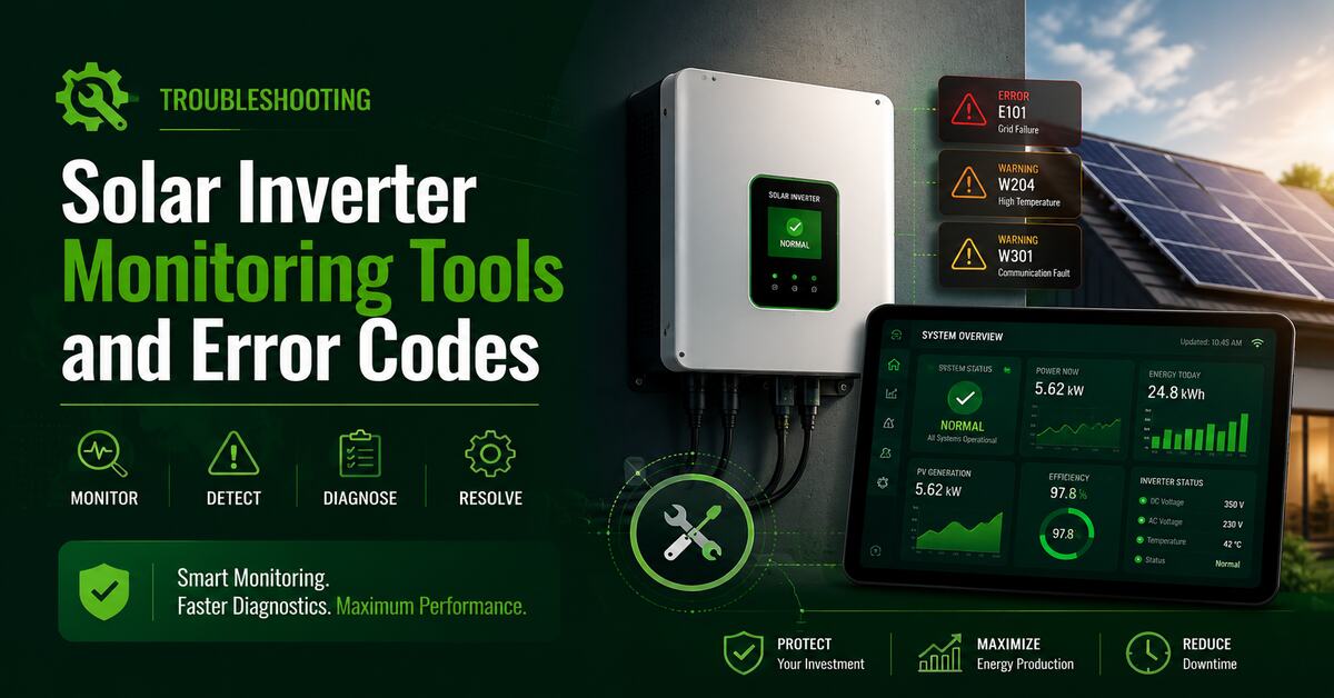
An inverter monitoring tool is a digital diagnostic system that tracks solar production, battery health, and grid performance in real-time. Troubleshooting inverter monitoring tools and error codes requires resolving physical hardware connections, decoding manufacturer-specific alerts, and stabilizing local network handshakes to restore continuous data logging.
Key Facts / At a Glance
- Over 90% of native inverter Wi-Fi modules only support 2.4GHz network bands; 5GHz routers are the leading cause of setup failure.
- Grid faults (like SolarEdge code 18×37 or 18×38) typically resolve automatically once utility voltage stabilizes below 253V.
- Isolation faults indicate physical ground leakage, requiring a multimeter resistance test aiming for at least 600 kΩ on single-phase strings.
- Reversing a third-party CT clamp causes the system to record power export as import, destroying consumption data accuracy.
- Arc fault alerts (such as AFCI or Fronius Error 240) should never be blindly reset without physically inspecting DC connectors for thermal damage.
How Do Inverter Monitoring Tools Actually Work?
Inverter monitoring relies on a continuous, four-stage data pipeline from your solar panels to the manufacturer’s cloud servers. When any stage of this pipeline breaks, the system displays an “Offline” status, even if the inverter is successfully generating AC power.
- Data Collection: Internal sensors measure metrics like DC input voltage, AC output current, grid frequency, and ambient heatsink temperature.
- Data Transmission: A physical data logger (integrated or external) packages this telemetry. It transmits the data via Wi-Fi, Ethernet, Cellular LTE, or hardwired RS485 Modbus.
- Cloud Processing: Manufacturer servers aggregate the raw data packets, apply time-stamps, and calculate cumulative energy yields.
- User Interface: The mobile app or web portal pulls this processed data, rendering the visual graphs and pushing push-notifications for fault alerts.
What Are the Main Types of Monitoring Hardware?
The hardware dictating how your inverter communicates falls into three distinct categories: integrated cards, external dongles, and third-party monitors. Identifying your hardware type is the first step in diagnosing communication failures.
- Integrated Wi-Fi/Ethernet Cards: Built directly into the inverter chassis. They typically update data in 5 to 15-minute intervals and are included at no extra cost with modern high-quality string inverters.
- External Plug-and-Play Dongles: USB or proprietary serial port sticks attached to the exterior of the inverter. They offer similar 5 to 15-minute intervals, cost between $50 and $150, and can be swapped without opening the live inverter chassis.
- Third-Party Energy Monitors: Independent CT (Current Transformer) clamps attached directly to the main electrical mains (e.g., Emporia Vue, Sense). They provide 1-second real-time tracking but cannot read internal inverter error codes.
Hardware Comparison Matrix
| Monitoring Type | Pros | Cons | Best For |
| Manufacturer Built-in | Native error codes; direct firmware updates; zero hardware setup. | Slow refresh rates; loses data if home Wi-Fi drops. | Average homeowners wanting basic health checks. |
| Cellular Dongles | Highly reliable; independent of local Wi-Fi; works in remote areas. | Requires ongoing subscription fees; slower data speeds. | Commercial sites; rural properties; landlords. |
| Third-Party CT Monitors | True real-time consumption tracking; monitors individual appliance loads. | Cannot read internal inverter faults; requires panel wiring. | Tech enthusiasts; off-grid users optimizing loads. |
How Do You Commission a New Monitoring Connection?
Commissioning a monitoring tool takes about 15 minutes and requires establishing a direct local connection to the inverter before authenticating it to the cloud. Follow this standard sequence to bring a disconnected system back online.
Before You Start: You will need a smartphone, your home Wi-Fi password, and the inverter’s default installer password (often 00000a, admin, or printed on the dongle label).
- Hardware Verification: Ensure the communication antenna or dongle is securely seated. Verify the inverter is receiving both DC (from panels) and AC (from the grid) power.
- Local Hotspot Connection: Turn off mobile data on your phone. Open Wi-Fi settings and connect to the inverter’s local broadcasted network (usually starting with
AP_, the brand name, or the serial number). - App Initialization: Open the manufacturer app or a mobile browser and navigate to the default gateway IP (commonly
10.10.100.254or192.168.0.5). Enter the administrator credentials. - Network Handshake: Scan for your home 2.4GHz Wi-Fi network. Enter your password exactly, as these fields are strictly case-sensitive.
- Cloud Verification: Save the settings. Wait for the dongle’s link LED to turn solid green or blue. Verify that the system shows “Online” on your standard user dashboard.
How to Decipher Critical Inverter Error Codes?
Error codes are the inverter’s active defense mechanism, triggering a physical relay disconnect when unsafe voltage, ground leakage, or arcing is detected. Understanding these codes dictates whether a simple restart is safe or if professional repair is mandatory.
1. Grid Faults (Over/Under Voltage & Frequency)
- Common Codes: 18×37, 18×38 (SolarEdge), Err 102, Grid Volt High, W001.
- Meaning: The utility grid voltage has spiked above or dropped below local safety thresholds. In standard 230V/240V systems, inverters are legally required to shut down if voltage exceeds 253V.
- Root Cause: Neighboring solar systems pushing grid voltage up during peak sun, or degraded utility street transformers.
2. Isolation Faults (Ground Faults)
- Common Codes: ISO Fault, 03x9a, 18×86 (SolarEdge), 475 (Fronius), Riso Low.
- Meaning: Current is leaking from the DC side of the solar array into the physical racking system or earth ground.
- Root Cause: Damaged wire insulation, water ingress inside rooftop DC connectors, or chewed cables. Acceptable resistance values are typically 200 MΩ for trunk cables and 600 kΩ for single-phase strings.
3. DC Overvoltage and Arc Faults
- Common Codes: Arc Fault, AFCI, 240/241/242 (Fronius), 18xC (SolarEdge), PV Overvolt.
- Meaning: The DC string voltage is dangerously high, or micro-sparking (arcs) are detected along a wire joint.
- Root Cause: Poorly crimped MC4 connectors, corrosion, or incorrect string sizing. Never reset an arc fault without physically verifying the connectors.
4. Hardware and Communication Faults
- Common Codes: Comm Error, Relay Fault, E21, Internal Error.
- Meaning: Internal mechanical components have failed, or the control boards cannot communicate via RS485 loops.
- Root Cause: Component aging, lightning surges, or corrupted system firmware requiring a manufacturer RMA (Return Merchandise Authorization).
Common Failure Modes and Diagnostics
| Issue / Symptom | Probable Cause | Diagnostic & Resolution Steps | Timeframe |
| App shows “Offline” but inverter runs. | Home router password changed or 5GHz band merged. | Power cycle router. Connect to local inverter AP hotspot to re-enter network credentials. | 15 Mins |
| System cycles on and off at noon. | Grid Overvoltage (above 253V) from high local solar output. | Check AC voltage logs. Request utility grid tap adjustment or inverter voltage profile widening. | 1–3 Days |
| “ISO Fault” triggers during heavy rain. | Water ingress in MC4 connectors. | Wait for drying. Run multimeter isolation resistance test across strings to ground. Replace leaky joints. | 2–4 Hours |
| Grid import reads as export. | Third-party CT clamp installed backwards. | Verify clamp arrow points toward the grid. Reverse physically or via software orientation settings. | 20 Mins |
What Are the Most Common Pitfalls to Avoid?
The most expensive troubleshooting mistakes involve misconfigured network bands and reversed polarity during hardware swaps. Avoid these frequent errors to maintain system uptime:
- Using 5GHz Wi-Fi Networks: Over 90% of inverter Wi-Fi modules lack 5GHz hardware. Attempting to link to a combined 2.4/5GHz band often results in a connection failure loop. Create a dedicated 2.4GHz guest network for the inverter.
- Reversing Polarity During Battery Swaps: Reconnecting DC cables backwards during a battery upgrade can instantly destroy internal inverter MOSFETs and capacitors. Always use a multimeter to confirm polarity before seating the cables.
- Mismatched CT Clamp Directionality: When installing Emporia or GivEnergy CT clamps, putting the sensor backward flips consumption data. You can verify this by checking night-time data; if it shows export when solar is offline, the clamp is backwards.
- Ignoring Firmware Warnings: Delaying critical updates can prevent the monitoring tool from patching security vulnerabilities or fixing handshake bugs with updated iOS/Android operating systems.
Which Monitoring Setup Should You Choose?
Your ideal monitoring setup depends on your site’s internet reliability and your need for real-time load automation. There is no single correct approach, but matching the hardware to the user profile prevents daily frustration.
For Everyday Homeowners
Stick to the native manufacturer-provided application (e.g., Fronius Solar.web, Enphase Enlighten). It provides zero-cost health updates, automated emails when faults occur, and ensures you retain standard warranty coverage paths without complex configuration.
For Off-Grid and Tech Enthusiasts
Deploy an independent third-party monitoring system (like Emporia) alongside local network integrations like Home Assistant via Modbus TCP. This enables 1-second automation triggers, allowing you to automatically dump excess solar generation into water heaters or EVs before battery clipping occurs.
For Commercial Operators and Landlords
Pay upfront for dedicated Cellular LTE tracking dongles. This completely eliminates tenant Wi-Fi access dependencies, stabilizes continuous uptime reporting, and ensures your fleet maintenance logs remain unified across multiple properties without relying on local routers.
Frequently Asked Questions
Why does my inverter show a green light but the app is offline?
A green light indicates the inverter is successfully generating AC power and pushing it to the grid. The app is offline because the separate Wi-Fi communication dongle has lost its connection to your home router, requiring a network credentials reset.
Can I use a Wi-Fi extender for my solar monitoring dongle?
Yes. Inverters are often installed in garages or on exterior walls where router signals degrade. A standard 2.4GHz Wi-Fi extender or a powerline ethernet adapter will effectively bridge the connection gap to the monitoring tool.
What is the acceptable resistance for an isolation fault test?
When testing an isolation fault with a multimeter, standard industry thresholds require at least 200 MΩ for trunk cables, 600 kΩ for single-phase strings, and 1 MΩ for commercial three-phase strings to be considered safe.
How do I test if my CT clamp is broken?
To verify the physical functionality of a CT clamp, disconnect it from the main incoming tails and test the positive and negative conductors using a multimeter. A healthy standard clamp should return a reading between 240 and 250 ohms.
How long does it take for cloud data to refresh?
Built-in Wi-Fi and cellular dongles aggregate data in batches, updating the cloud dashboard every 5 to 15 minutes to save bandwidth. Only third-party CT clamps (like Sense or Emporia) offer true 1-second real-time refreshing.