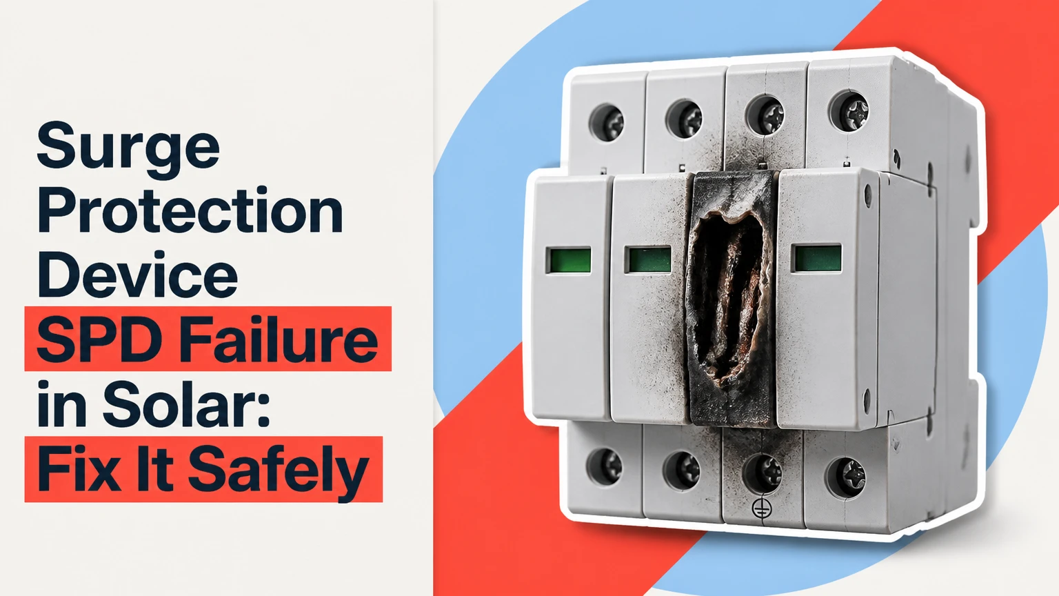
A surge protection device (SPD) failure in a solar photovoltaic system means the device has disconnected, shorted, or lost effective surge protection after electrical stress, overheating, aging, or incorrect installation. Replace a failed SPD promptly, but first isolate the circuit and investigate voltage rating, grounding, wiring length, lightning exposure, and inverter fault evidence.
Key Facts / At a Glance
A PV SPD must be rated for the solar array’s maximum operating voltage, polarity, and DC fault current.
A red or blank status indicator usually means the SPD cartridge has disconnected and requires replacement.
A solar installation normally needs coordinated protection on the DC side and the AC side.
A failed SPD does not prove that lightning caused the failure; switching surges, leakage, heat, and incorrect sizing can produce the same result.
Long connecting conductors increase residual voltage because conductor inductance adds voltage during a fast surge.
Never test or replace an energized solar SPD. PV strings can remain dangerous in daylight, even when the inverter is off.
What Is a Solar SPD?
A solar SPD is a protective device that limits transient overvoltage and diverts surge current through a bonding and grounding network. PV systems use dedicated DC SPDs between array circuits and inverter inputs, while AC SPDs protect the inverter output, distribution equipment, and connected loads.
The device remains high impedance at normal voltage. During a transient, its internal protection element conducts briefly, reducing the voltage imposed on insulation and electronics. The SPD does not absorb all lightning energy, stop a direct strike, or replace system bonding, lightning protection, fuses, or overcurrent protection.
Most photovoltaic products use metal oxide varistors (MOVs), sometimes combined with gas discharge tubes (GDTs). MOVs respond rapidly but experience cumulative electrical and thermal stress. A thermal disconnector separates an overheated MOV from the circuit, reducing fire risk when the component reaches an unsafe condition.
The International Electrotechnical Commission addresses low-voltage surge protective devices in IEC 61643-11 and PV-specific SPDs in IEC 61643-31. Product certification, national wiring rules, and the equipment manufacturer’s instructions determine whether a particular model is acceptable at a site.
How Does a Solar SPD Work?
A solar SPD changes from high resistance to controlled conduction when transient voltage exceeds its protection threshold. The surge current then follows the shortest available path through the SPD conductors and bonding network, while the protected equipment sees a lower residual voltage.
The sequence is fast:
- Normal operation: The SPD draws only its specified leakage current.
- Transient arrival: Lightning-induced voltage or switching voltage rises across the protected conductors.
- Conduction: The MOV or GDT conducts surge current.
- Voltage limitation: The device holds voltage below its stated protection level, called (U_p).
- Disconnection: Excessive energy, sustained overvoltage, or aging can activate the thermal separator.
- End-of-life indication: A mechanical window changes color, or an auxiliary contact reports failure.
A PV SPD faces a harder interruption problem than an AC SPD. DC current does not naturally pass through a zero-voltage point every half-cycle, so a failed DC device can sustain an arc unless its design includes the correct photovoltaic interruption rating.
A useful practitioner rule is to judge protection by the complete path, not the cartridge alone. A premium SPD connected with long, narrow, poorly bonded conductors can provide weaker equipment protection than a correctly installed midrange device.
“Lightning is a serious threat to electronic systems because of the magnitude and rapidity of its current,” wrote lightning researcher Martin A. Uman in The Lightning Discharge. The observation explains why a millisecond-scale device response does not compensate for poor routing or bonding.
Why Do Solar SPDs Fail?
Solar SPDs fail because surge energy, continuous overvoltage, heat, leakage, fault current, or installation defects exceed the device’s design conditions. Lightning is one cause, but repeated smaller transients and an incorrectly selected voltage rating often produce premature failure without visible storm damage.
| Failure cause | Typical evidence | Electrical mechanism | Corrective action |
|---|---|---|---|
| Lightning or induced surge | Blackened housing, tripped protection, storm correlation | MOV energy absorption exceeds design | Replace SPD and inspect bonding, array, inverter |
| Ucpv too low | Repeated failures, heating, insulation alarms | MOV conducts near normal string voltage | Recalculate cold-weather maximum Voc |
| AC SPD installed on DC | Arc damage, melted terminals, immediate failure | Incorrect DC interruption capability | Install certified PV DC SPD |
| Sustained grid overvoltage | AC SPD failure without lightning | MOV remains under prolonged stress | Measure supply and check utility voltage |
| Loose or long conductors | Warm terminals, damaged leads, high residual voltage | Resistance and inductance increase stress | Reterminate and shorten conductors |
| Moisture or heat | Corrosion, condensation, brittle enclosure | Leakage current and thermal aging increase | Correct enclosure and ventilation problems |
The most common sizing mistake is comparing (U_{cpv}) only with today’s measured string voltage. The design must use the array’s maximum open-circuit voltage at the site’s lowest expected cell temperature, then account for the manufacturer’s configuration requirements. Cold weather raises Voc.
A second mistake is assuming a green indicator proves the entire surge path is healthy. The indicator usually reports the cartridge’s thermal state. It does not verify conductor torque, bonding continuity, earthing impedance, polarity, or protection coordination.
Which SPD Type Does a Solar System Need?
Type 1 SPDs handle partial lightning current where a structure has a formal external lightning protection system or where a direct lightning-current threat is expected. Type 2 SPDs handle induced lightning transients and switching surges. Type 1+2 products combine both classifications when the installation design permits one coordinated device.
| SPD classification | Test waveform | Typical rating metric | Solar application |
|---|---|---|---|
| Type 1 | 10/350 microsecond | (I_{imp}), often 12.5 kA per pole | Service entrance or lightning-current boundary |
| Type 2 | 8/20 microsecond | (I_n), commonly 5-20 kA; (I_{max}), commonly 20-40 kA | PV combiner, inverter DC input, AC distribution |
| Type 1+2 | 10/350 and 8/20 microsecond | (I_{imp}), (I_n), and (I_{max}) | Sites needing combined protection |
| Type 3 | Combination-wave equipment test | Low discharge capacity | Close to sensitive loads, never as primary PV protection |
Type labels do not determine the correct voltage rating. A Type 2, 1,000 V DC product can still be unsuitable if the array polarity arrangement, short-circuit current, or grounding system does not match its data sheet.
For many residential rooftop systems, a coordinated Type 2 DC SPD near the inverter and Type 2 AC SPD at the inverter output are typical. A building with external lightning protection, overhead supply conductors, or a high lightning density may need Type 1 or Type 1+2 equipment after a lightning-risk assessment.
How Should Ucpv Be Selected?
Select (U_{cpv}) above the array’s maximum operating voltage under the manufacturer’s grounding and polarity configuration, while keeping the protection level (U_p) low enough for the inverter’s impulse withstand rating. The correct value comes from the PV design, not from a generic “600 V” or “1,000 V” label.
| PV system condition | Typical system voltage | SPD selection checkpoint | Frequent error |
|---|---|---|---|
| Small residential string | 300-600 V DC | Compare (U_{cpv}) with cold-weather Voc | Using nominal 400 V as maximum |
| Modern rooftop string | 600-1,000 V DC | Verify inverter maximum DC input | Choosing 600 V for a 1,000 V design |
| Commercial array | 1,000-1,500 V DC | Check IEC 61643-31 certification | Applying a low-voltage residential module |
| Ungrounded or floating array | 600-1,500 V DC | Match mode of protection and system topology | Assuming grounded-array wiring applies |
Installers should also check (I_{scpv}), the prospective PV short-circuit current the SPD can safely interrupt, and the manufacturer’s required backup fuse or circuit breaker. An SPD with high surge-current capacity but insufficient short-circuit protection remains an unsafe choice.
Where Should SPDs Be Installed?
PV SPDs belong at electrical boundaries where surge voltage can enter or where conductor length allows a dangerous voltage difference to develop. Typical systems place protection at the array or combiner, the inverter DC terminals, the inverter AC output, and sometimes the main service equipment.
A long cable between an array SPD and inverter can allow substantial residual voltage at the inverter. IEC installation practice commonly targets total connecting conductor lengths of about 0.5 m where feasible. The exact arrangement depends on the equipment, conductor routing, and national code.
| Installation point | Protected equipment | Typical device | Design detail |
|---|---|---|---|
| Rooftop combiner | String wiring and combiner electronics | Type 2 DC | Keep positive, negative, and bond paths short |
| Inverter DC input | DC input stage and MPPT electronics | Type 2 DC | Match voltage, polarity, and (I_{scpv}) |
| Inverter AC output | Inverter and distribution board | Type 2 AC | Coordinate with upstream service SPD |
| Main service panel | Building loads and inverter connection | Type 1+2 or Type 2 AC | Follow utility and panel coordination rules |
| Data or communications entry | Monitoring gateway and network equipment | Signal SPD | Match Ethernet, RS-485, or proprietary interface |
Do not create separate, poorly bonded earth rods and assume they improve surge protection. During a fast event, different ground potentials can force surge current through inverter communication cables, module frames, or AC conductors.
MOV, GDT, or Hybrid: Which Technology Fits?
MOV-based PV SPDs provide rapid voltage limitation and are common on DC circuits, while GDTs provide low leakage and high impulse-current handling but may have higher response and follow-current considerations. Hybrid designs combine technologies to balance leakage, energy handling, and voltage protection.
| Technology | Typical response behavior | Leakage characteristic | Main limitation | Common use |
|---|---|---|---|---|
| MOV | Nanosecond-scale conduction | Small continuous leakage | Ages with surge and heat | PV DC and AC protection |
| GDT | Very low leakage before firing | Near-zero standby leakage | Higher sparkover voltage | High-energy or coordinated stages |
| MOV plus GDT | Fast first-stage limitation | Lower leakage than MOV alone | More complex coordination | Service and commercial systems |
| Pluggable MOV cartridge | Same MOV behavior | Replaceable module | Requires matching base | Residential and C&I maintenance |
A pluggable cartridge costs more initially but reduces replacement time and wiring disturbance. A fixed monobloc device may cost less and occupy less space, but a failed unit normally requires full conductor isolation and reconnection.
What Happens After SPD Failure?
After solar SPD failure, the protected circuit may continue producing power, but the inverter and array no longer have the intended transient protection. A disconnected SPD leaves an open protective path; a shorted or damaged SPD can create an insulation fault, trip overcurrent protection, or overheat its enclosure.
Possible symptoms include:
- Red, black, or blank status window.
- Inverter alarms such as insulation resistance, ground fault, or surge protection failure.
- Repeated DC fuse or AC breaker operation.
- Scorch marks, cracked plastic, odor, or melted terminals.
- Monitoring alerts from a dry-contact or digital status output.
- A failed communication gateway after a nearby storm.
A failed SPD does not automatically mean the inverter is damaged. The inverter may remain fully functional if the SPD diverted the event before disconnecting. However, a post-failure inspection should include inverter input protection, string insulation, combiner fuses, communications equipment, and visible module or optimizer damage.
How Do You Diagnose Failure?
Diagnose a solar SPD by isolating the system, reading the status indicator, checking inverter records, inspecting wiring, and testing the surrounding circuit with rated instruments. A multimeter resistance test across an installed SPD is not a reliable general-purpose pass-or-fail method because MOVs can appear high resistance, and connected circuits can distort readings.
Safe Diagnostic Sequence
- Record the symptoms. Photograph the indicator, enclosure, inverter alarm, and monitoring timestamp.
- Shut down under the manufacturer’s procedure. Open AC isolation, DC isolation, and string-level devices as applicable; verify absence of voltage with a properly rated meter.
- Inspect the module. A red indicator, mechanical disconnect, cracked housing, or heat discoloration normally requires replacement.
- Check the data sheet. Confirm voltage class, system configuration, backup protection, and replacement cartridge part number.
- Inspect conductors. Look for loose terminals, insulation damage, corrosion, excessive length, sharp bends, and missing bonding.
- Test the system. A qualified technician can perform insulation resistance, polarity, continuity, and voltage tests according to the inverter and code requirements.
- Investigate recurrence. Measure supply voltage, inspect lightning protection, review storm history, and check whether other SPDs failed at the same time.
Only a manufacturer-approved tester or a specified procedure should be used for live SPD testing. Applying a generic insulation tester directly to an SPD can damage the device and invalidate the diagnosis.
How Can a Failed SPD Be Replaced?
Replace a failed modular solar SPD only after the affected circuit is isolated, voltage absence is verified, and the replacement cartridge matches the original system requirements. A trained electrician can often replace a pluggable cartridge in 15-30 minutes; a fixed device commonly takes 1-2 hours because conductors must be removed and reterminated.
| Replacement stage | Typical time | Required verification | Failure risk |
|---|---|---|---|
| Identify cartridge | 5-10 minutes | Manufacturer part number and voltage | Installing an AC module on DC |
| Isolate equipment | 10-20 minutes | AC and DC voltage absence | Assuming nighttime isolation is sufficient |
| Replace module | 5-15 minutes | Correct orientation and seating | Loose or mismatched cartridge |
| Inspect wiring | 10-20 minutes | Torque, routing, bonding | Reusing heat-damaged conductors |
| Recommission | 10-30 minutes | Inverter status and SPD indicator | Leaving remote alarm unwired |
The replacement is not complete when the indicator turns green. The installer must verify terminal torque, conductor routing, backup overcurrent protection, enclosure sealing, and remote signaling. If the old device failed violently, replacing only the cartridge can leave the original cause unresolved.
What Are the Cost and Lifespan?
Typical residential replacement cost is about $40-$90 for a DC or AC cartridge, while a commercial Type 1+2 device commonly costs $150-$400 before labor. A modular replacement may total $100-$250 installed; fixed-unit replacement can rise to $250-$600 when access, testing, and rewiring are included.
| Item | Typical product cost | Typical labor or time | Cost variable |
|---|---|---|---|
| Residential Type 2 cartridge | $20-$50 | 15-30 minutes | Brand and voltage class |
| Residential complete SPD | $40-$90 | 30-60 minutes | AC or DC configuration |
| Commercial Type 2 unit | $80-$250 | 45-90 minutes | Current rating and signaling |
| Type 1+2 commercial SPD | $150-$400 | 1-2 hours | (I_{imp}), enclosure, access |
| Inspection after lightning | Not product-specific | 1-3 hours | Roof access and testing scope |
A three-to-seven-year service life is a practical planning range, not a guaranteed expiration date. Local lightning frequency, utility quality, temperature, enclosure conditions, and the number of transient events determine actual life. A green indicator does not mean an SPD has a fixed remaining number of years.
Which Configuration Fits the Site?
Residential rooftop systems usually need coordinated Type 2 DC and AC SPDs, while commercial, lightning-exposed, and battery-equipped sites require a wider protection review. The correct configuration depends on array voltage, building lightning protection, cable distance, service arrangement, and whether the site has sensitive communications or storage electronics.
| Site scenario | DC protection | AC protection | Additional consideration |
|---|---|---|---|
| Residential rooftop, 600 V array | Type 2 PV SPD | Type 2 panel SPD | Short inverter connections |
| Residential rooftop, 1,000 V array | Type 2, 1,000 V PV SPD | Type 2 AC SPD | Cold-weather Voc calculation |
| Building with lightning system | Type 1+2 or coordinated Type 1 and 2 | Type 1+2 at service | Lightning protection zones |
| Ground-mount commercial array | Type 1+2 or Type 2 by risk design | Type 1+2 at service | Long underground or overhead runs |
| Microinverter array | Module or trunk-level PV protection | Type 2 AC SPD | Manufacturer-specific location |
| PV plus battery storage | PV DC and inverter AC SPDs | Battery-rated SPD where specified | Battery voltage and fault rating |
Remote contacts are worthwhile on commercial systems because a failed cartridge can otherwise remain unnoticed until the next transient. Connect the alarm output to the inverter, building management system, or SCADA platform only after confirming contact ratings and fail-state logic.
Do Battery Systems Need Their Own SPD?
Battery systems may need a separate DC SPD because battery voltage, grounding arrangement, enclosure, and fault current differ from PV array conditions. A PV-rated SPD should not automatically be installed on a battery circuit unless its data sheet explicitly covers that battery voltage and circuit topology.
Battery manufacturers often specify whether surge protection is permitted, where it is installed, and what backup fuse is required. Lithium battery systems also require isolation procedures that account for stored energy after AC and PV disconnects are open. Follow the battery and inverter manuals rather than adapting a rooftop PV diagram.
Common Installation Mistakes
The most damaging installation mistakes involve incorrect voltage selection, excessive conductor length, missing coordination, and assuming an earth rod alone provides a low-impedance surge path.
- Using nominal voltage instead of maximum Voc: Recalculate at the lowest design temperature.
- Mixing AC and DC modules: Confirm the marking, certification, polarity, and DC interruption rating.
- Leaving long loops in SPD conductors: Route conductors directly and keep the combined path near 0.5 m where practical.
- Ignoring backup protection: Install the specified fuse or breaker for the SPD’s short-circuit environment.
- Bonding only the SPD: Bond module frames, inverter enclosure, combiner, rails, and service equipment into one coordinated network.
- Replacing without investigating: Check lightning exposure, utility voltage, moisture, and terminal condition before recommissioning.
A counterintuitive field finding is that a low-resistance ground rod does not by itself guarantee low surge voltage. Fast surge performance depends on impedance, conductor geometry, bonding continuity, and equipotential construction, not resistance measured at ordinary test frequency alone.
FAQ
Can a solar SPD fail without a lightning strike?
Yes. A solar SPD can fail from repeated switching surges, utility overvoltage, heat, moisture, leakage current, or an incorrectly low (U_{cpv}) rating. A storm-free failure therefore requires electrical inspection rather than an automatic lightning claim, especially when multiple sites on the same feeder report similar damage.
Can a failed SPD damage a solar inverter?
A failed SPD can damage an inverter if the device conducts improperly, develops an arc, or fails to divert a transient before disconnection. Many SPDs disconnect thermally and leave the inverter operating, but the inverter’s input protection, insulation alarms, and surge records should still be checked after failure.
Is a red SPD indicator always dangerous?
A red indicator usually means the replaceable protection element has reached end of life and no longer provides rated surge protection. The module may be electrically open rather than immediately hazardous, but the circuit should be treated as unprotected until a qualified person replaces the device and inspects the cause.
Can I test a PV SPD with a multimeter?
A basic multimeter cannot reliably confirm that a PV SPD will clamp at its specified voltage or handle its rated surge current. A technician can use visual inspection, isolation tests, manufacturer-approved equipment, and system tests, but ordinary resistance readings should not determine whether the device is serviceable.
Do solar panels need surge protection in every installation?
The required protection depends on wiring rules, risk assessment, array layout, building exposure, and equipment instructions. SPDs are especially important where cable runs are long, lightning exposure is high, overhead conductors exist, or the inverter and monitoring equipment have significant replacement cost.
Will a warranty cover a failed solar SPD?
Warranty coverage varies by manufacturer and failure cause. A claim may require installation records, product certification, photographs, surge or inverter logs, and evidence that the array voltage and backup protection matched the instructions. Lightning damage is often handled differently from premature failure caused by incorrect installation.
Conclusion
Surge protection device SPD failure solar problems require two actions: replace the failed protective device and identify why it failed. Match (U_{cpv}), (I_{scpv}), SPD type, polarity, backup protection, grounding, and conductor routing to the actual PV and inverter design. A correct replacement restores protection; a like-for-like replacement without diagnosis can repeat the failure.