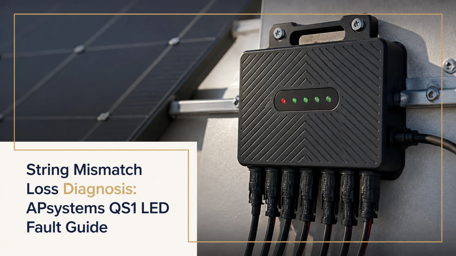
String mismatch loss diagnosis identifies whether unequal solar-panel current or voltage is reducing output, rather than assuming an APsystems QS1 LED fault proves a panel mismatch. The QS1 LED primarily reports DC startup, AC production, communication, and ground-fault states. Comparing panel-level EMA data, environmental conditions, and the affected microinverter usually separates mismatch from wiring or grid problems.
Key Facts at a Glance
An APsystems QS1 uses one multicolor LED, so color, blink speed, and interval must be read together.
Slow green generally indicates production and ECU communication; fast green generally indicates production without recent ECU communication.
Flashing red indicates that the QS1 has DC power but is not exporting AC power.
Solid red indicates a ground-fault condition that requires inspection by a qualified solar professional.
A dark LED during daylight can indicate absent panel DC input, disconnected wiring, or failed microinverter hardware.
A QS1 can continue producing when its ECU communication fails, but monitoring and alerts may be unavailable.
What Is String Mismatch Loss Diagnosis?
String mismatch loss diagnosis is the process of determining whether panels with unequal electrical behavior are limiting solar production. In a conventional series string, the lowest-current module can constrain current through other modules. The APsystems QS1 changes that electrical context because each QS1 input uses module-level power conversion, so one weak panel normally affects its own input rather than an entire multi-panel string.
The phrase “string mismatch” is therefore often applied too broadly. A QS1 showing fast green, flashing red, or solid red is reporting an operational state, not automatically proving mismatch loss. A mismatch investigation compares the affected panel with neighboring panels under similar irradiance, tilt, orientation, shading, and temperature.
What can cause actual mismatch loss?
Actual mismatch can result from partial shade, different module orientations, unequal aging, soiling, snow cover, module degradation, connector resistance, or a panel with a different electrical rating. In a QS1 installation, the most useful evidence is a persistent panel-level power difference rather than a single LED color.
| Suspected condition | Typical electrical symptom | QS1 or EMA evidence | Best confirmation |
|---|---|---|---|
| Partial shade | Output falls during repeatable shade window | One input underperforms at the same time daily | Shade map and production comparison |
| Soiling or snow | Reduced current across one panel | Lower daily watt-hours with normal voltage trend | Visual inspection from ground |
| Module degradation | Gradual seasonal decline | One panel remains below peers in similar weather | Installer testing and historical EMA data |
| Connector resistance | Intermittent or heat-related loss | Output changes after rain or high load | Qualified technician inspection |
| Orientation difference | Consistent lower yield | Panel follows a different irradiance profile | Array layout and production modeling |
| QS1 AC fault | Zero output from multiple inputs | Red LED or repeated AC-related alarm | AC-side diagnosis by technician |
Why does a QS1 complicate the diagnosis?
The QS1 is a four-module microinverter, commonly rated around 1,200 VA depending on regional version and grid configuration. Its four DC inputs are converted at module level, while its AC output connects to a branch circuit. Consequently, a fault in one input may not look like a conventional string-current limitation.
A panel-level comparison is more informative than comparing only the branch circuit total. If all four panels assigned to one QS1 stop producing, investigate AC output, grid conditions, or the microinverter before blaming four simultaneous panel mismatches.
What Do the APsystems QS1 LED Patterns Mean?
The APsystems QS1 LED pattern identifies the broad operating state, but the EMA monitoring platform or ECUApp is needed for detailed voltage, frequency, and alarm information. Read the LED during daylight, observe the pattern for at least 30 seconds, and record whether the condition affects one QS1 or the whole array.
| LED color and pattern | Likely QS1 state | Production status | First diagnostic action |
|---|---|---|---|
| One quick red, then three short green blinks | DC startup initialization | Not yet confirmed as stable production | Wait for normal operating pattern |
| Slow green, approximately 10-second interval | Producing and communicating | AC production expected | Compare EMA output with nearby units |
| Fast green, approximately 2-second interval | Producing without recent ECU communication | Production may continue | Check ECU power, network, and location |
| Flashing red, approximately 10-second interval | DC present, AC export unavailable | No production from that QS1 | Check solar breakers and utility status |
| Solid red | Ground-fault detector condition | Production inhibited | Stop DIY electrical work and call a technician |
| No visible light in daylight | No DC input or hardware failure | No production expected | Check from ground, then arrange testing |
The exact blink timing can vary with model revision and viewing conditions. Use the QS1 manual for the installed regional version, especially where the product label identifies QS1, QS1A, or a country-specific electrical configuration.
What does one red and three green blinks mean?
One quick red blink followed by three short green blinks normally indicates QS1 startup initialization. The sequence means the microinverter has received DC input and is initializing its internal control process; it does not by itself prove that the unit has synchronized with the grid or begun exporting power.
If the QS1 remains in startup, check whether the array is in daylight and whether the AC branch circuit is energized. A normal restart can also include a grid-stability waiting period of approximately five minutes before production resumes.
Why Does Fast Green Mean Communication Loss?
Fast green usually means the APsystems QS1 is producing power but has not communicated with the ECU gateway for more than approximately 60 minutes. The most common causes are an unplugged ECU, excessive distance between gateway and array, radio interference, or a communication path disrupted by equipment relocation.
Fast green is therefore different from flashing red. Fast green can represent a monitoring failure while the microinverter continues offsetting household consumption. Flashing red represents an AC production problem.
| Communication symptom | Likely location of fault | Production implication | Check |
|---|---|---|---|
| One QS1 fast green | Local radio path or device registration | One unit may still produce | Compare nearby QS1 devices |
| Entire array absent in EMA | ECU, internet, or account issue | Production may continue | Check ECU LEDs and power supply |
| New QS1 missing after replacement | UID not registered or handshake incomplete | Device may produce locally | Allow 10-30 minutes, then verify UID |
| Data delayed by several minutes | Monitoring refresh or internet latency | Production may be normal | Compare inverter LED with historical data |
| Fast green after ECU relocation | Reduced Zigbee signal path | Local production may continue | Move ECU closer, following installation rules |
APsystems documentation describes ECU-based communication over a 2.4 GHz wireless network in applicable systems. Metal enclosures, concrete walls, competing wireless devices, and long array-to-gateway distances can reduce reliability.
How Can You Reset a QS1 Safely?
A homeowner should reset the system only from safe, accessible disconnects and breakers. Do not climb onto a roof, remove energized MC4 connectors, open the microinverter enclosure, or measure exposed conductors without appropriate training and equipment.
Before you start
| Requirement | Typical value or condition | Homeowner limit | Technician requirement |
|---|---|---|---|
| Minimum daylight | Bright enough for panel DC generation | Observe LED only | Electrical testing permitted under procedure |
| Reset time | At least 3 minutes de-energized | Use disconnects only | Verify isolation and stored energy |
| Grid reconnection delay | Approximately 5 minutes | Wait before judging failure | Confirm voltage and frequency |
| ECU registration | Approximately 10-30 minutes | Check app after waiting | Add or verify microinverter UID |
| Required tools | Phone, flashlight, notebook | Ground-level inspection | Rated meter and PPE for electrical tests |
Step 1: Record the evidence
Write down the LED color, blink interval, time of day, weather, and affected device location. Capture EMA screenshots before changing system state, because a reset can clear the immediate visual sequence without correcting the underlying fault.
Success checkpoint: You have a timestamped pattern and know whether one QS1, one branch, or the whole system is affected.
Common mistake: Recording only “red light.” Solid red and flashing red indicate materially different conditions.
Step 2: Check accessible AC disconnects
Inspect the solar breaker and any external AC disconnect from ground level or inside the permitted electrical area. If a breaker is tripped, switch it fully off and then on once, provided there is no burning smell, water intrusion, heat damage, repeated tripping, or visible conductor damage.
Success checkpoint: The breaker remains on and the system begins its normal restart sequence.
Common mistake: Repeatedly resetting a breaker that trips again. Recurrent tripping indicates a fault requiring professional diagnosis.
Step 3: Check the ECU and monitoring path
Confirm that the ECU power adapter is connected, its status lights are active, and the home network or internet service is operating. Do not interpret a stale EMA dashboard as proof that the microinverters are not producing.
Success checkpoint: EMA begins receiving current device data after its normal refresh and communication interval.
Common mistake: Replacing a QS1 because the app is offline when the physical LED shows fast green production.
Step 4: Allow the grid-stability delay
After AC power returns, wait approximately five minutes before evaluating the LED. Anti-islanding protection prevents the microinverter from exporting power until voltage and frequency remain within permitted limits.
Success checkpoint: A healthy unit transitions through startup and reaches slow green production.
Common mistake: Declaring failure after 30 seconds. The reconnection timer is an intentional safety behavior.
Step 5: Escalate red faults correctly
If flashing red persists after one safe breaker check, arrange qualified testing of the AC branch, trunk connector, utility voltage, and microinverter alarms. If solid red persists, stop troubleshooting and have the array inspected for insulation, connector, moisture, and grounding faults.
Success checkpoint: A technician identifies and corrects the fault, then confirms normal operation through both LED state and monitoring data.
Common mistake: Pulling DC connectors apart in sunlight. APsystems’ QS1 manual warns, “Do not disconnect the DC wire connectors under load.” The warning addresses arc-flash, connector damage, and fire risk.
Does the Fault Affect One Unit or the Whole Array?
A single affected QS1 usually points toward a local device, connector, panel group, or branch connection, while a whole-array failure more often points toward the shared AC supply, utility grid, ECU, or system-level control issue. Scope is one of the fastest ways to reduce diagnostic uncertainty.
| Observed scope | More likely causes | Less likely cause | Diagnostic priority |
|---|---|---|---|
| One panel input low | Shade, soiling, module, DC connector | Utility outage | Compare panel-level EMA data |
| All four inputs on one QS1 low | QS1 hardware, AC connection, local grid issue | Four independent mismatches | Check device and branch |
| Several QS1 units on one branch offline | Branch breaker, trunk cable, connector | Individual panel defects | Inspect shared AC path |
| Entire array offline | Utility outage, main solar breaker, ECU or site issue | One-panel mismatch | Check service and disconnects |
| EMA offline but LEDs green | ECU, internet, radio interference | Microinverter failure | Test monitoring path separately |
A counterintuitive field rule is that four dark or nonproducing inputs on one QS1 are rarely four independent panel failures. Shared electrical infrastructure deserves priority because the four inputs share the microinverter’s AC conversion and reporting functions.
What Causes Flashing Red on a QS1?
Flashing red generally means the APsystems QS1 has DC power but cannot produce AC output. A tripped breaker, disconnected AC trunk, utility outage, abnormal grid voltage or frequency, and damaged AC connector are common causes.
The QS1 may remain in this condition during a local blackout because anti-islanding protection prevents distributed generators from energizing a de-energized utility circuit. If neighboring household circuits are also without power, check the utility status before treating the QS1 as defective.
When should AC voltage be measured?
AC voltage should be measured by a qualified technician when the breaker is on but flashing red persists, especially if other branch devices appear normal. Regional systems may use approximately 240 V line-to-line in North American residential installations or approximately 208 V in some commercial or multi-unit configurations; the correct value depends on the service design and QS1 model.
A technician should test at the relevant disconnect, trunk, and branch points using equipment rated for the installation category. Homeowners should not probe T-junctions or open terminals with a multimeter, because the test exposes energized conductors and can create a short circuit.
What Causes Solid Red and a GFDI Fault?
Solid red generally identifies a ground-fault detector condition, meaning unwanted electrical leakage from the photovoltaic circuit toward ground has been detected. Damaged module insulation, wet or contaminated connectors, pinched DC cable, sharp racking edges, and incorrect termination can create the condition.
Ground-fault protection is a safety shutdown, not a nuisance status to bypass. A qualified installer should isolate the affected circuit, inspect cables and connectors, test insulation resistance where appropriate, and verify equipment grounding and sealing.
| Ground-fault source | Typical trigger | Why weather matters | Required response |
|---|---|---|---|
| Damaged module backsheet | Insulation breakdown | Moisture lowers insulation resistance | Professional module and insulation test |
| Wet MC4 connector | Water ingress or poor mating | Rain and dew increase leakage | Replace damaged connector pair |
| Pinched DC cable | Racking compression | Thermal movement worsens damage | Re-route and replace cable |
| Open unused QS1 input | Missing sealing cap | Rain enters exposed connector | Install manufacturer-compatible sealing cap |
| Poor equipment bonding | Missing grounding hardware | Humidity increases intermittent readings | Verify bonding path and hardware |
| Internal QS1 fault | Failed isolation component | Heat can increase recurrence | Manufacturer or technician evaluation |
An important distinction is that an unused input is not automatically a ground fault. The input must be sealed according to APsystems installation instructions, and the connector system must remain compatible with the specified environmental rating.
Can the QS1 Produce Power Without the ECU?
The APsystems QS1 can generally continue local power conversion when the ECU communication path is unavailable, provided the AC grid and DC inputs remain healthy. Without the ECU, the homeowner loses reliable panel-level reporting, historical data synchronization, remote alarms, and convenient confirmation of production.
The physical LED is not a substitute for production measurements. Slow green indicates the expected operating state, but it does not quantify wattage or prove that every one of the four module inputs is producing equally.
| Diagnostic source | Information available | Typical delay | Main limitation |
|---|---|---|---|
| QS1 physical LED | Broad operating state | Immediate | No voltage, current, or wattage |
| EMA portal | Historical and panel-level data | Often minutes | Requires ECU and network path |
| ECUApp local interface | Device alarms and commissioning data | Near local session | Installer access and compatible ECU needed |
| AC clamp or meter | Branch current and voltage | Immediate | Qualified-person electrical work |
| PV insulation test | Leakage and insulation condition | Test session | Requires isolation and specialized procedure |
How Long Should QS1 Recovery Take?
A normal QS1 recovery commonly takes three separate intervals: a three-minute power-down period during a controlled reset, about five minutes for grid reconnection, and roughly 10-30 minutes for a newly registered microinverter to appear through ECU communication. These are typical operational intervals, not guarantees for every firmware or regional model.
If the LED remains flashing red after the reconnection period, the issue is probably not an ordinary startup delay. If EMA remains incomplete after 30 minutes but the LED is fast green, investigate communication or registration rather than AC production.
LED or EMA, Which Diagnostic Source Is Better?
EMA is better for confirming panel-level mismatch because it exposes comparative production data, while the QS1 LED is better for immediate broad-state observation when the gateway or internet is unavailable. The most reliable diagnosis uses both sources, followed by electrical testing when the evidence points to wiring or grid conditions.
The LED cannot distinguish a weak panel from a disconnected input. EMA trends can reveal that distinction, but stale or missing telemetry can create a false impression of low production.
A practical interpretation rule is simple: use the LED to classify the operating state, EMA to compare inputs and history, and a qualified technician’s instruments to prove an electrical fault.
What Can a Homeowner Safely Check?
A homeowner can check system status from ground level, inspect accessible breakers, review utility outage information, confirm ECU power, photograph visible damage, and compare EMA data from similarly oriented panels. A homeowner should not remove connectors, open the QS1, climb an unsafe roof, or test live terminals.
Stop immediately if you see melted plastic, cracked connector bodies, exposed copper, water inside electrical equipment, smoke, a burning odor, repeated breaker trips, or a solid-red ground-fault indication. Keep people away from the affected area and contact the installer, utility, or emergency services when conditions indicate immediate danger.
Which observations are useful to a technician?
Provide the QS1 serial number, LED pattern, timestamp, weather, affected panel positions, breaker status, EMA alarms, and whether the problem affects one device or several. Photos should show equipment labels and visible cable routing without requiring anyone to touch the installation.
This evidence reduces unnecessary truck rolls. It also helps distinguish a replacement-device registration issue from a failed microinverter.
Repair or Replace a QS1?
Repair is usually preferable when the problem is a breaker, connector, communication gateway, or weather-related termination defect. Replacement becomes more reasonable when a qualified technician confirms internal QS1 failure, the unit is outside warranty, and a compatible replacement can be commissioned with the existing branch design.
The QS1 product line is older and has been followed by newer APsystems microinverter families such as the DS3 series. Compatibility depends on electrical ratings, trunk connectors, ECU support, regional approvals, and installer configuration, so a newer unit is not automatically a plug-in substitute.
| Decision factor | Repair existing QS1 | Replace with compatible QS1 | Upgrade to newer family |
|---|---|---|---|
| Typical equipment cost | $0-$150 for minor parts | Approximately $180-$275 typical refurbished range | Often higher, quote required |
| Labor range | $150-$300 typical service visit | $150-$300 typical installation labor | Site-specific design and labor |
| Commissioning time | 30-90 minutes after access | 30-90 minutes plus 10-30 minutes registration | Often several hours for redesign |
| Main advantage | Preserves existing architecture | Minimizes array changes | Adds current product support |
| Main limitation | Older hardware remains | Availability may be limited | Compatibility and cost review needed |
These figures are typical market ranges, not manufacturer quotes. Warranty coverage, roof access, travel distance, local labor rates, and replacement availability can change the total substantially.
Common Diagnostic Mistakes and Their Fixes
Mistake 1: Calling every low panel “string mismatch”
A low panel in EMA may reflect shade, soiling, a failed input, or stale telemetry. Compare the panel against neighbors during the same 15-30 minute irradiance window and inspect the trend across several clear days before assigning a mismatch diagnosis.
Mistake 2: Resetting before recording the alarm
A reset can remove the visible symptom while leaving no useful timeline for the installer. Record the LED pattern, EMA alarm, weather, and scope first.
Mistake 3: Disconnecting MC4 connectors under sunlight
DC connectors can sustain an arc when separated under load. Turn off the appropriate AC disconnect first, then leave DC isolation and connector work to a qualified technician following the manufacturer procedure.
Mistake 4: Treating fast green as a production failure
Fast green usually points to missing ECU communication, not immediate loss of conversion. Verify branch production independently before purchasing a microinverter.
Mistake 5: Repeatedly resetting a solid-red QS1
A solid-red condition can indicate insulation leakage that returns when moisture or voltage rises. Repeated resets do not repair damaged cable, module insulation, or connector sealing.
Mistake 6: Assuming the app is current
EMA data may be delayed, absent, or incomplete when the ECU loses network access. Compare the dashboard timestamp with the physical LED and the utility meter before concluding that generation has stopped.
The Bottom Line
String mismatch loss diagnosis on an APsystems QS1 begins with panel-level production comparison, not LED color alone. Slow green usually supports normal production, fast green points toward ECU communication loss, flashing red points toward an AC or grid production problem, and solid red requires professional ground-fault investigation.
Use the LED for immediate classification, EMA for historical and module-level comparison, and qualified electrical testing for proof. Check accessible breakers and gateway power, allow the approximately five-minute reconnection period, and never disconnect photovoltaic connectors under load. A safe diagnosis is more valuable than a fast reset.
FAQ
Does a QS1 LED work at night?
The QS1 LED depends on DC input from the photovoltaic modules, so a dark LED at night does not prove hardware failure. Evaluate the device in daylight, preferably when irradiance is sufficient for startup, and compare the result with EMA history from the same period.
Can shading look like a microinverter fault?
Shading can make one input appear weak without creating a QS1 fault LED. A predictable production drop that follows the shade pattern points toward an environmental mismatch, while a sudden zero-output condition, red LED, or simultaneous failure of all four inputs requires electrical investigation.
Why does only one of four QS1 panels underperform?
One underperforming input can result from module damage, shade, soiling, a connector problem, or an input-level fault. Compare voltage and production trends through EMA where available, then have a technician test the module and DC path if the difference persists under similar sunlight.
Should an unused QS1 input be capped?
Yes. An unused QS1 input should be sealed with the compatible protective cap specified by the installation instructions. An exposed connector can admit moisture and contamination, increasing the chance of insulation or ground-fault problems, although an uncapped input is not by itself proof of an active fault.
How do I find the affected QS1 on the roof?
Use the EMA device list and serial number records to map the microinverter to its panel group. If monitoring is unavailable, an installer can use commissioning records, branch layout, and device-level testing. Do not access a steep or wet roof solely to read an LED.
Is a flashing red QS1 dangerous?
Flashing red indicates that the QS1 has DC power but is not exporting AC, commonly because of a grid, breaker, or AC connection issue. The condition still involves energized photovoltaic equipment. Perform only accessible checks, avoid exposed wiring, and use a qualified technician for electrical diagnosis.