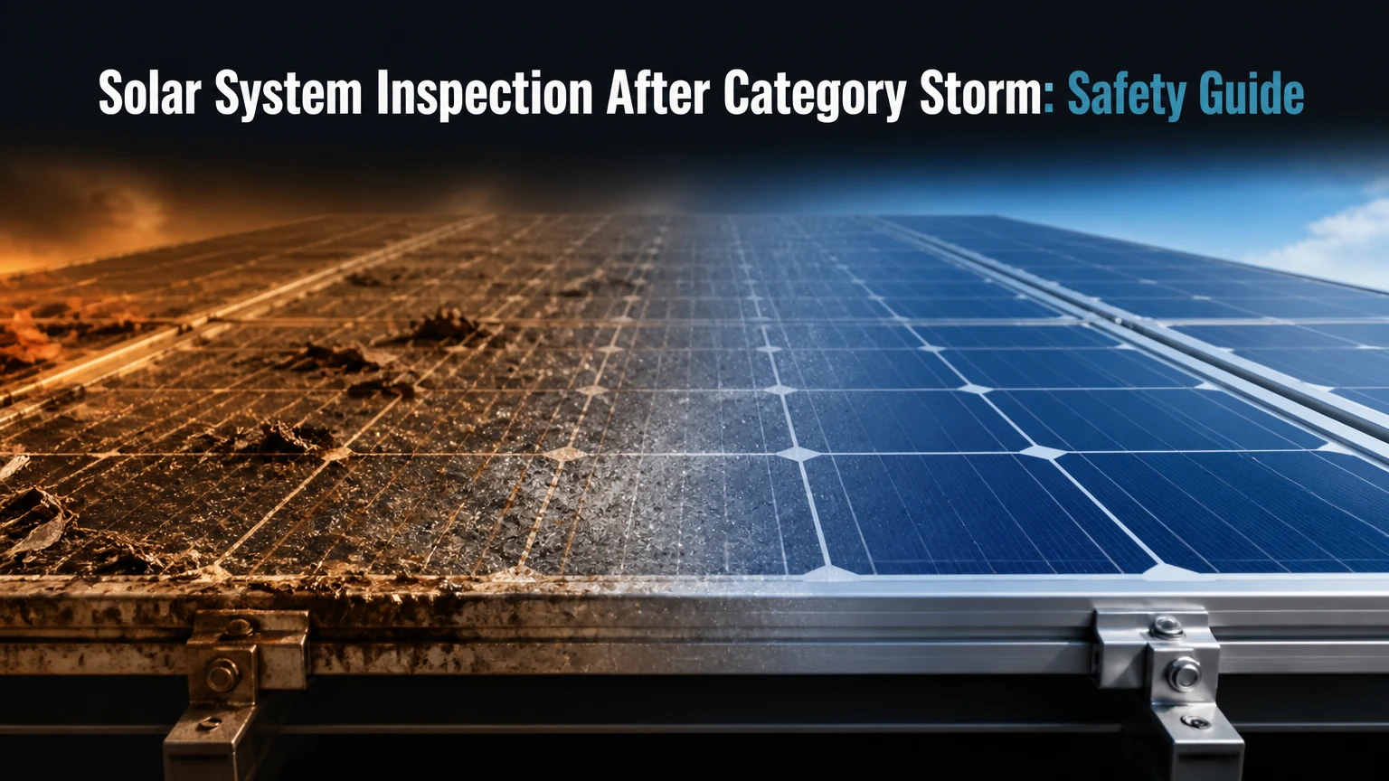
A solar system inspection after a Category storm verifies whether photovoltaic modules, racking, roof attachments, wiring, inverters, and batteries remain safe before the system is energized. The correct sequence is remote review, utility and equipment isolation, ground-level observation, professional mechanical inspection, electrical testing, documentation, and controlled recommissioning.
Key Facts at a Glance
- A Category 1 hurricane has sustained winds of at least 74 mph, or 119 km/h, while Category 5 begins at 157 mph, or 252 km/h, under the Saffir-Simpson Hurricane Wind Scale.
- Homeowners should perform only remote monitoring and ground-level observation after severe storm damage.
- Broken module glass, exposed conductors, flooded equipment, loose racking, and damaged roofs require a complete lockout and qualified service personnel.
- Solar modules can produce DC voltage whenever light reaches them, even when the inverter display is off.
- A typical residential post-storm inspection costs about $250-$600, while larger commercial audits commonly cost $1,500-$5,000 or more.
- Clamp torque, insulation resistance limits, test voltages, and recommissioning procedures must follow the module, racking, inverter, battery, and local electrical-code requirements.
What Does a Post-Storm Solar Inspection Check?
A post-storm solar inspection checks five connected systems: the PV modules, mechanical mounting assembly, roof or ground structure, electrical conductors and protection equipment, and energy storage equipment. Inspectors compare current condition and production against pre-storm records, then classify hazards before recommending repair or controlled restart.
The inspection is more than a panel visual check. Wind can shift rails without breaking glass, hail can damage cells beneath intact laminates, and floodwater can contaminate insulation or battery enclosures without leaving obvious exterior marks. A complete report therefore combines photographs, monitoring data, structural observations, electrical measurements, and equipment serial numbers.
The storm category alone does not determine damage. Local wind direction, flying debris, hail size, storm surge, roof age, mounting design, and installation quality often matter more than the headline wind category. A Category 2 storm that removes nearby trees can create more array damage than a stronger storm with no debris impact.
What does the inspection classify?
| Finding class | Typical evidence | Operating decision | Required next action |
|---|---|---|---|
| Immediate hazard | Broken glass, exposed copper, flooded inverter, loose rail | Keep PV and affected circuits locked out | Qualified electrical or structural assessment |
| Functional damage | String underproduction, cracked module, failed rapid shutdown device | Do not resume normal operation until evaluated | Electrical testing and targeted repair |
| Roof or structural concern | Lifted flashing, rafter movement, roof collapse signs | Keep roof access restricted | Roofing or structural engineer review |
| Minor condition | Surface debris, light frame scuff, displaced label | No energized work by homeowner | Document, then clean or repair safely |
| No visible damage | Stable racking, intact modules, normal telemetry | Controlled recommissioning may be possible | Professional verification where required |
This classification is a triage tool, not a substitute for the National Electrical Code, local authority requirements, manufacturer instructions, or an engineer’s assessment.
What Should Happen Before Anyone Touches the System?
The first action is to prevent contact with damaged equipment and establish whether utility, PV, battery, or structural hazards exist. Do not climb onto a wet roof, move storm debris near conductors, reset a faulted inverter, or disconnect a battery enclosure after flooding.
The Occupational Safety and Health Administration advises workers to “Treat all power lines as energized.” That principle applies to downed utility conductors and suspected solar wiring. Water can spread the hazard across metal roofing, standing water, fences, conduit, and equipment cabinets.
Call the electric utility immediately if service lines, meters, poles, or the service entrance appear damaged. Call emergency services for fire, smoke, arcing, a collapsing roof, or a battery that is hot, swelling, hissing, leaking, or producing an unusual odor.
Before-start requirements
| Requirement | Residential system | Commercial system | Why it matters |
|---|---|---|---|
| Minimum homeowner activity | Monitoring app and ground view | Remote control-room review | Avoids unnecessary exposure |
| Typical inspection duration | 2-5 hours on site | 4 hours to multiple days | Array size and access change scope |
| Typical inspection price | $250-$600 | $1,500-$5,000 or more | Structural and electrical testing drive cost |
| Useful records | One-line diagram, photos, production history | Asset map, string map, test history | Enables pre-storm comparison |
| Required specialists | Solar electrician, roofer if needed | Electrical contractor, engineer, thermographer | Multiple hazards may overlap |
How Should the Inspection Begin?
Begin with a remote evidence review before visiting the property. Monitoring portals such as Enphase Enlighten, SolarEdge Monitoring, SMA Sunny Portal, and Tesla applications can show the time of production loss, inverter alarms, string imbalance, battery state, and communications failure.
A complete baseline includes the last 30-90 days of daily production, inverter event logs, module and inverter serial numbers, a single-line diagram, array photographs, roof photographs, and the latest service report. Export screenshots or portal data before repairs overwrite the original fault history.
A production drop does not prove module damage. Grid failure, utility curtailment, communications loss, inverter shutdown, a tripped breaker, and storm cloud cover can produce similar dashboard symptoms. Compare array output with utility availability and the inverter’s event timestamps.
Remote review checklist
- Record the storm date, approximate peak wind, hail reports, flooding, and nearby debris impacts.
- Export monitoring data from seven days before through the inspection date.
- Save every ground-fault, arc-fault, isolation, rapid-shutdown, overtemperature, and battery alarm.
- Confirm whether the outage affects the whole array, one string, individual microinverters, or only the internet connection.
- Review the original design voltage, string count, battery chemistry, equipment location, and rapid-shutdown architecture.
- Photograph the monitoring screen with the date and error message visible.
Step 1: Isolate the Property and Solar Equipment
A qualified person should isolate the affected energy sources using the site-specific shutdown procedure, utility requirements, and equipment labels. PV modules remain capable of generating DC electricity in daylight, so an inverter power switch alone does not make damaged conductors safe.
The exact shutdown order varies by equipment design. Some systems require opening the AC disconnect first, others specify battery isolation before inverter shutdown, and emergency responders may use a different procedure. Follow the installed placard and manufacturer manual rather than a generic internet sequence.
Do not open a wet inverter, battery cabinet, combiner box, junction box, or disconnect enclosure. Do not remove module connectors under load. A technician must verify absence of hazardous voltage using rated instruments and a procedure suitable for the system.
Step 2: Perform a Ground-Level Hazard Survey
A ground-level survey identifies hazards without requiring roof access. Walk the perimeter only when safe, looking for detached modules, hanging conduit, broken glass, fallen trees, shifted equipment, waterline marks, and exposed wiring.
Keep people and pets away from the array and debris field. The often-cited 35-foot clearance is not a universal solar rule; required approach distances depend on voltage, utility direction, worker qualification, site conditions, and local rules. Treat the clearance around downed utility lines as the utility or emergency authority directs.
Ground-level checklist
| Area | Inspect for | Evidence to record | Stop-work trigger |
|---|---|---|---|
| Array perimeter | Glass, clips, rails, detached modules | Wide and close photographs | Live or hanging conductor |
| Roof edge | Flapping conduit, lifted fascia, water discharge | Direction and attachment point | Sagging roof or loose array |
| Inverter wall | Impact, waterline, damaged disconnect | Serial number and alarm lights | Smoke, heat, liquid, arcing |
| Ground equipment | Flood sediment, shifted cabinet, exposed cable | Water depth and sediment line | Standing water near equipment |
| Battery location | Deformation, leakage, odor, heat | Cabinet condition and alarms | Thermal event or swelling |
| Utility interface | Meter, service mast, overhead lines | Utility damage from public area | Downed or damaged service line |
Do not sweep broken solar glass into a pile before photographing it. Insurance adjusters and manufacturers may need impact patterns, module labels, and the relationship between debris and the array.
Step 3: Confirm Roof and Structural Safety
Roof safety must be established before a technician performs a roof-level solar inspection. Stormwater can weaken roof decking, hide openings, and make metal, tile, and asphalt surfaces slippery; displaced modules can also add concentrated loads to damaged areas.
A roofing professional or structural engineer may need to inspect the roof independently of the solar contractor. The solar installer can evaluate racking and attachments, but that does not automatically qualify the installer to certify roof framing, trusses, parapets, or building envelope damage.
Structural inspection points
- Check for rail deflection, twisting, uplift, displaced feet, elongated bolt holes, and missing fasteners.
- Inspect module frames for bending, laminate separation, corner damage, and clamp migration.
- Examine flashings, sealant, standoffs, L-feet, ballast blocks, roof membranes, and exposed rafters.
- Look beneath array edges for punctures, lifted shingles, broken tiles, wet insulation, and new interior stains.
- Compare attachment positions with the original plan set and pre-storm photographs.
- Verify that rooftop walkways and access paths remain stable before carrying equipment.
Should clamps be retorqued after a storm?
Clamps should be checked against the specific racking manufacturer’s torque specification, not a universal 8-12 Nm assumption. Torque values vary by clamp model, bolt size, material, lubricant, rail type, module frame, and installation instructions, and indiscriminate retightening can damage threads or module frames.
A calibrated torque wrench documents applied torque, but torque alone does not prove that a roof attachment remains structurally sound. A shifted rail, pulled lag, cracked substrate, or elongated hole needs mechanical assessment and sometimes replacement rather than tightening.
Step 4: Inspect Modules, Racking, and Roof Interfaces
The mechanical inspection links each visible defect to a likely failure mode and operating consequence. A starburst fracture indicates impact, while a displaced clamp, scratched rail, or bent frame may indicate uplift or sliding even when the laminate appears intact.
Inspectors should photograph each damaged module with its barcode or position identifier, then map the finding to the string or microinverter. Module-level records prevent a common claim error: documenting a damaged array without proving which serial-numbered components require replacement.
| Component | Storm damage indicator | Possible consequence | Verification method |
|---|---|---|---|
| Tempered glass | Starburst, long crack, missing section | Moisture entry and unsafe surface | Close visual photographs |
| Laminate | Bubbles, separation, yellowing, edge lift | Cell corrosion and insulation failure | Visual review and electroluminescence if justified |
| Frame | Bend, twist, corner separation | Clamp failure or water path | Straightedge, measurements, photographs |
| Rail | Deflection, twist, displaced splice | Uplift and module movement | Plan comparison and structural review |
| Clamp | Migration, missing bolt, frame mark | Module release or grounding issue | Manufacturer-specific inspection |
| Flashing | Lifted metal, torn seal, open penetration | Roof leakage | Roofer inspection and moisture review |
| Cable | Abrasion, crushed insulation, unsupported loop | Ground fault or arc fault | Visual review and electrical test |
A thermal camera can locate abnormal heating, but infrared imaging cannot reliably identify every micro-crack. Wind, irradiance variation, shading, soiling, bypass-diode behavior, loose connectors, and dissimilar string current can create thermal patterns that resemble cell damage.
Step 5: Complete Professional Electrical Testing
Electrical testing should follow visual and structural screening, because testing a physically damaged or wet circuit can create an arc, shock, or equipment failure. Qualified technicians typically verify DC polarity, string open-circuit voltage, operating current, insulation resistance, grounding and bonding continuity, disconnect condition, rapid-shutdown operation, and inverter fault status.
Open-circuit voltage, written as Voc, should be compared with the expected module count and temperature-adjusted design voltage. Short-circuit current, written as Isc, is not always the best field measurement because it requires a suitable instrument and controlled procedure; current clamp, operating-current, or I-V curve testing may be more appropriate.
Insulation-resistance testing requires equipment settings and pass criteria specified by the inverter and applicable code. A generic megohmmeter voltage or threshold can damage sensitive electronics or produce a misleading result if surge protection, optimizers, or batteries remain connected.
Electrical test sequence
- Confirm equipment isolation and identify every circuit.
- Disconnect or protect devices that the manufacturer excludes from insulation testing.
- Verify polarity and expected string voltage.
- Test insulation resistance from conductors to ground using approved settings.
- Compare operating current or I-V curves between equivalent strings.
- Test rapid shutdown, grounding, bonding, disconnects, and protective devices.
- Record instrument model, calibration status, test voltage, temperature, irradiance, and result.
- Reconnect only after the technician resolves abnormal readings.
What does an isolation fault mean?
An isolation fault usually means that current-carrying conductors have an unintended path to ground through wet insulation, a damaged connector, a pinched cable, a flooded junction box, a failed surge protector, or contaminated equipment. The correct response is lockout and circuit-level diagnosis, not repeated inverter resets.
Wet insulation can temporarily pass a test and later fail as heat, vibration, and moisture change. Technicians should isolate strings or branch circuits methodically, inspect connectors and cable routes, and retest after the damaged component dries only when the equipment manufacturer permits that procedure.
Step 6: Inspect Inverters, Disconnects, and Batteries
Inverters and disconnects need enclosure, seal, cable-entry, ventilation, surge-protection, and fault-history checks. A dry-looking cabinet can still contain corrosive contamination after floodwater or wind-driven rain entered through a damaged gasket.
Battery systems require a separate hazard assessment because lithium-ion and other storage technologies have different isolation, thermal, and emergency-response procedures. Do not operate, charge, discharge, or open a battery that has been submerged, physically deformed, punctured, exposed to saltwater, or reported by its manufacturer as damaged.
| Equipment | Safe visual check | Unsafe condition | Disposition |
|---|---|---|---|
| String inverter | Exterior impact, display, vents, conduit | Waterline, corrosion, smoke, fault | Keep isolated for manufacturer assessment |
| Microinverter array | Module position and branch cable route | Detached unit or damaged trunk cable | De-energized branch diagnosis |
| DC combiner | Door, gasket, fuses, cable glands | Water ingress or heat damage | Replace or test under procedure |
| Battery cabinet | Exterior, alarms, anchor points | Flooding, swelling, odor, heat | Emergency isolation and manufacturer guidance |
| AC panel | Breakers, enclosure, service connection | Water contamination or arcing | Licensed electrical inspection |
| Rapid shutdown device | Labels, status, wiring | Fault or inaccessible control | Functional test before restart |
A battery that appears to support backup loads during a brief test may still contain hidden damage. Controlled recommissioning must follow the battery manufacturer’s procedure and may require a service diagnostic, insulation test, capacity test, or replacement decision.
How Should Findings Be Documented for Insurance?
Document condition before cleanup, removal, drying, or repair. A defensible claim file connects the storm event, component identity, location, visible damage, electrical evidence, repair estimate, and pre-storm performance.
Use wide photographs to establish location, medium photographs to show the assembly, and close photographs for cracks, labels, connectors, fasteners, waterlines, and impact marks. Preserve damaged modules and equipment when practical, and record who removed each item and where it was stored.
Claim documentation checklist
- Storm date, wind or hail report, flood depth, and nearby property damage.
- Pre-storm and post-storm monitoring exports.
- Array map with module, inverter, optimizer, and battery identifiers.
- Geotagged photographs with timestamps when available.
- Written inspection report with measurements and test conditions.
- Roofing, electrical, structural, and equipment-replacement estimates.
- Manufacturer warranty terms and installer workmanship warranty.
- Utility outage records and permit or interconnection documents.
Insurance coverage differs by policy, deductible, peril exclusions, depreciation rules, and flood provisions. A solar warranty generally covers manufacturing defects, not necessarily wind, hail, flood, or installation damage.
Which Inspection Method Fits the System?
Manual inspection is the better foundation for most residential systems because it can verify cable routing, enclosure condition, attachment movement, and string-level electrical behavior. Drone thermography is valuable for large or inaccessible arrays, but it cannot verify bolt torque, roof penetration integrity, connector engagement, or battery condition.
The strongest commercial workflow combines remote monitoring, drone or handheld infrared screening, targeted electrical tests, and ground or roof inspection. Thermal imaging should narrow the diagnostic area rather than replace mechanical and electrical verification.
| Method | Typical scope | Typical cost | Main strength | Main limitation |
|---|---|---|---|---|
| Ground visual survey | Residential exterior | $0 homeowner observation | Finds obvious hazards safely | Cannot verify hidden electrical damage |
| Manual technician audit | 3-20 kW array | $250-$600 | Checks attachments and circuits | Requires safe roof access |
| Drone RGB survey | Large or steep roof | $75-$200 add-on | Maps displacement without walking roof | Wind and aviation restrictions apply |
| Drone thermal survey | Commercial multi-string array | $100-$500 or more | Screens many modules quickly | Needs suitable irradiance and interpretation |
| Handheld thermography | Targeted modules and cabinets | $100-$200 add-on | Confirms localized heat patterns | False positives need verification |
| Engineering assessment | Structural or major-loss case | Project-specific | Evaluates building and attachment capacity | Higher cost and longer report time |
Thermography needs adequate solar irradiance, stable operating conditions, and trained interpretation. A shaded, wet, heavily soiled, or disconnected array can produce poor thermal evidence.
How Much Does a Post-Storm Inspection Cost and Take?
A typical residential inspection costs $250-$600 and takes two to five hours on site when access is safe and no major structural engineering is required. Commercial inspections commonly cost $1,500-$5,000 or more, while drone surveys, thermal imaging, electrical testing, emergency access, and engineering reports increase the total.
A written report usually takes one to seven business days after fieldwork, depending on image processing, string testing, engineering review, and insurer requirements. Immediate safety hazards should be communicated verbally before the final report is complete.
| Scope | Typical field time | Typical report time | Typical price |
|---|---|---|---|
| Ground-level homeowner review | 30-60 minutes | Same day notes | $0 |
| Small residential visual inspection | 1-2 hours | 1-3 business days | $150-$350 |
| Residential electrical and roof review | 2-5 hours | 2-7 business days | $250-$600 |
| Commercial visual and thermal survey | 4-16 hours | 3-7 business days | $1,500-$5,000+ |
| Structural engineering review | 1-3 site visits | 5-15 business days | $500-$3,000+ |
| Emergency battery or flood assessment | Project-specific | Immediate hazard notice | Project-specific |
These are typical practitioner ranges, not regulated prices. Array size, travel, roof complexity, access restrictions, storm demand, and testing scope create substantial variation.
What Common Post-Storm Symptoms Mean
Post-storm symptoms must be interpreted with system architecture and utility status. A dark inverter, low production, or missing monitoring data may indicate a communications problem rather than physical array damage, but only qualified testing can separate those possibilities safely.
Complete production loss
Possible causes include utility outage, open AC disconnect, inverter damage, rapid-shutdown activation, flooded equipment, or a communications failure. Check utility status and the monitoring portal remotely, then leave physical diagnosis to a qualified technician if the system shows fault codes or visible damage.
One string underproduces
A damaged module, connector, optimizer, cable, bypass diode, shade change, or blown fuse can reduce one string. Compare equivalent strings under similar irradiance and use I-V tracing or module-level diagnostics to locate the defect.
Isolation or ground-fault alarm
Moisture, insulation abrasion, contaminated connectors, damaged surge protection, and crushed cables are common causes. Keep the circuit isolated and avoid repeatedly restarting the inverter, because intermittent faults can worsen as the system dries or heats.
Inverter communicates but output is low
Communication proves that the electronics can report data, not that every module produces correctly. Hail damage, cracked cells, shading from shifted modules, soiling, and thermal bypass-diode faults can reduce output while the inverter remains online.
Battery will not charge
The battery may be protecting itself because of temperature, isolation, enclosure damage, state-of-charge limits, grid conditions, or a management-system fault. Do not bypass the battery management system or substitute a charger without manufacturer approval.
Common Mistakes and How to Fix Them
Climbing the roof to inspect broken modules
Problem: Wet roofing, hidden openings, and unstable racking create fall and collapse risks.
Fix: Photograph from ground level and use a qualified roofer or solar technician after structural clearance.
Resetting a faulted inverter repeatedly
Problem: A reset can re-energize a wet connector, compromised conductor, or damaged surge device.
Fix: Record the code, isolate the system, and request circuit-level testing.
Using a universal torque number
Problem: Generic 8-12 Nm guidance can conflict with the actual clamp or rail specification.
Fix: Use the installed manufacturer manual and document the calibrated tool reading.
Cleaning before photographing
Problem: Removed glass, branches, and mud can destroy evidence of impact or flooding.
Fix: Photograph first, preserve representative debris, then clean only after documentation.
Treating a thermal image as proof
Problem: Shade, soiling, loose connectors, and irradiance variation can mimic cell damage.
Fix: Correlate thermal anomalies with visual inspection, string data, and electrical testing.
Testing flooded equipment
Problem: Energizing wet electrical or battery equipment can cause shock, arc flash, fire, or irreversible damage.
Fix: Keep equipment isolated and follow the manufacturer’s flood-damage replacement or evaluation procedure.
Can a Solar System Be Re-Energized After a Category Storm?
A solar system can be re-energized only after qualified personnel verify structural stability, dry and intact enclosures, conductor integrity, insulation performance, protection-device operation, and utility permission where required. Normal monitoring or an inverter that starts successfully does not prove the system is safe.
Controlled recommissioning typically proceeds from physical clearance to enclosure inspection, circuit testing, protective-device verification, inverter startup, and monitored operation. Technicians should record startup alarms, voltage and current behavior, battery response, and output over an initial observation period.
Stop recommissioning if an alarm returns, a connector heats, voltage is abnormal, the roof shifts, water appears, or the battery produces heat, odor, noise, or leakage. The system remains locked out until the cause is resolved.
Expert Rules of Thumb
- A production graph is not a safety certificate. Monitoring can identify when output changed, but it cannot detect every loose clamp, damaged roof penetration, or compromised insulation.
- The first failed component may not be the visible component. A broken module can damage a connector or cable below it, while a harmless-looking scuff can conceal cell fractures.
- Storm severity and inspection urgency are different variables. Flooding, fire, downed utilities, and battery damage require immediate controls even when module glass looks intact.
- Replace rather than dry certain equipment. Floodwater, especially saltwater, can leave conductive and corrosive deposits inside disconnects, inverters, and battery assemblies.
- Match the report to the claim. An insurer needs identifiable damage and causation evidence, while a technician needs measurements and repair instructions. A report that provides only photographs serves neither purpose well.
FAQ
How soon after a hurricane should solar panels be inspected?
Perform a ground-level safety check as soon as emergency authorities allow access, but delay roof entry until the roof and utilities are safe. A qualified solar inspection commonly occurs within 24-72 hours for visible damage and within 7-14 days for broader commercial documentation, subject to access, weather, and insurer requirements.
Do solar panels still work after hail damage?
Solar panels may continue producing after hail cracks glass or cells, but continued operation can increase moisture intrusion, hot-spot formation, and electrical risk. Intact output does not clear hail-damaged modules. Photograph the impact pattern, isolate visibly damaged circuits, and obtain module-level electrical or thermal evaluation.
Can microinverter systems be inspected differently?
Microinverter systems require module-level and branch-circuit review rather than only string-voltage testing. Inspectors should examine each module, trunk cable, connector, grounding path, and microinverter status, then compare module production in the monitoring portal. A failed communications gateway can hide otherwise useful module-level data.
Does homeowners insurance cover storm-damaged solar panels?
Homeowners insurance may cover storm damage when the policy covers the peril and the system is part of the insured property, but deductibles, flood exclusions, endorsements, installation status, and depreciation rules vary. File promptly, preserve damaged equipment, and compare the policy with manufacturer and installer warranty terms.
Should damaged solar panels be washed after the storm?
Damaged panels should not be washed before evidence is recorded or electrical safety is established. Water, pressure washing, and contact with broken glass can worsen damage or expose the person cleaning it to electrical and sharp-edge hazards. A qualified contractor should determine whether safe cleaning is appropriate.
The Bottom Line
A solar system inspection after Category storm conditions should begin with remote monitoring, utility awareness, and a complete lockout decision, not roof access or an inverter reset. Ground-level evidence, structural review, manufacturer-specific electrical testing, battery precautions, and claim-quality documentation determine whether the system can return to service safely. Perform only observation as a homeowner, and use qualified solar, roofing, electrical, or engineering professionals for all energized, roof-level, structural, and storage work.