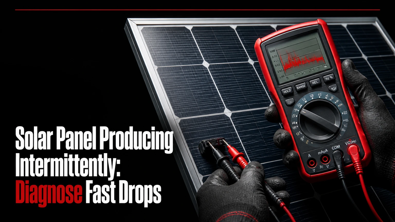
A solar panel producing intermittently may be responding normally to moving clouds, changing shade, or snow, or it may indicate an electrical, inverter, grid, or monitoring fault. Rapid output changes during clear skies, repeated inverter restarts, sudden voltage steps, and unexplained data gaps require separate tests because each symptom points to a different failure source.
Key Facts at a Glance
Moving clouds can change photovoltaic output within seconds without indicating a failed panel.
A clear-sky power drop that repeats at similar times often indicates shading, temperature, grid voltage, or inverter behavior.
A string inverter can lose substantial output when one module, connector, diode, or string develops a fault.
Microinverters isolate module-level failures, but they cannot make shaded or dirty modules produce full power.
Grid overvoltage can repeatedly disconnect a compliant inverter under anti-islanding protection.
A battery smooths delivered power, but it does not repair a defective module, inverter, connector, or grid connection.
What Does Solar Panel Producing Intermittently Mean?
Intermittent solar production means photovoltaic output changes irregularly rather than following the expected daylight curve. Normal production rises after sunrise, peaks near solar noon, and falls toward sunset, while abnormal behavior appears as repeated collapses, spikes, restarts, or low-output plateaus during otherwise usable sunlight.
Solar output is governed primarily by plane-of-array irradiance, module temperature, electrical operating point, and system limits. The National Renewable Energy Laboratory PVWatts model uses irradiance, temperature, system losses, and inverter behavior to estimate production, which explains why a perfectly smooth real-world curve is unrealistic.
The practical distinction is timing and repeatability. A cloud crossing the array creates a weather-linked change. A 20-minute cycle on a cloudless afternoon, especially when the inverter reports a fault, deserves electrical diagnosis.
Normal Variation Versus Fault Behavior
| Pattern | Typical duration | Likely explanation | First check |
|---|---|---|---|
| Gradual morning increase | 30-180 minutes | Sunrise and changing sun angle | Compare clear-day curve |
| Abrupt drop with visible cloud | 5 seconds-10 minutes | Moving cloud or cloud edge | Compare sky and irradiance |
| Output loss at the same clock time | 15-120 minutes | Tree, chimney, pole, or seasonal shade | Perform shading audit |
| Repeated restart every few minutes | 2-15 minutes per cycle | Grid voltage, thermal fault, or inverter error | Read inverter log |
| Zero output with normal DC voltage | 1 hour or longer | AC disconnect, inverter, or grid issue | Check AC status |
| Small monitoring gaps with stable power | 1-30 minutes | Wi-Fi, cellular, gateway, or server issue | Compare inverter display |
How Does Photovoltaic Output Change?
Photovoltaic cells produce direct current when photons create charge carriers in semiconductor material. Irradiance mainly controls current, while module temperature has a stronger effect on voltage, so an array can receive sunlight and still deliver less power as its operating temperature rises.
The inverter continually searches for the maximum power point, the voltage and current combination that produces the highest available DC power. Rapid irradiance changes, incompatible string orientations, sensor errors, firmware problems, or a restricted voltage window can make that search unstable.
A useful field rule is to compare power with weather, DC voltage, DC current, AC voltage, and inverter temperature at the same timestamp. Power alone cannot identify the cause. For example, a current collapse with stable voltage often points toward shade or a connection issue, whereas a normal DC input followed by zero AC output points toward the inverter or grid.
What Is the Difference Between Irradiance and Power?
| Variable | What changes it | Typical electrical effect | Diagnostic meaning |
|---|---|---|---|
| Irradiance | Clouds, shade, dust, snow | Current changes quickly | Environmental loss likely |
| Cell temperature | Sun load, roof ventilation, ambient heat | Voltage falls as temperature rises | Heat-related derating possible |
| DC voltage | Module count, temperature, diode state | String operating point shifts | Wiring, diode, or MPPT clue |
| DC current | Irradiance, mismatch, connector resistance | Available power falls | Shade, dirt, or connection clue |
| AC voltage | Utility conductors and local demand | Inverter may disconnect | Grid interaction likely |
| Inverter temperature | Enclosure heat and airflow | Power derating or shutdown | Ventilation or installation issue |
Which Environmental Changes Are Normal?
Clouds, moving shadows, snow cover, heavy soiling, and wind-blown obstructions can cause legitimate short-term production changes. Environmental fluctuation is normal when output changes match the irradiance reaching the array and the inverter does not generate repeated fault events.
Fast-moving cumulus clouds can create sharp rises at cloud edges as reflected light temporarily increases irradiance. A south-facing array can also experience shade from a chimney or tree only during a narrow seasonal window. Snow is different: partial snow cover can create both reduced irradiance and uneven module temperatures, while a fully covered array may produce almost nothing.
Dust usually creates a gradual loss, not rapid cycling. A loose plastic sheet, leaf, bird nesting material, or wind-blown branch can create intermittent shade that appears and disappears with wind.
How Can You Separate Weather From Equipment Failure?
- Compare the system chart with a nearby weather station or a second, unshaded array.
- Check whether every module or string changes at the same time.
- Review inverter alarms during the event.
- Observe the array at several times during the suspected shade window.
- Compare clear days with similar temperature and utility demand.
If all strings fall together during cloud movement, the environment is the leading explanation. If one string falls while other strings remain stable, localized shade, a connector, module, diode, or optimizer deserves attention.
Why Does Output Drop Under Clear Skies?
A clear-sky production drop usually comes from shade, high module temperature, inverter derating, grid voltage, a DC connection, a module-level power electronic device, or a monitoring error. The repeated timing of the event is often more informative than the size of the power loss.
Grid voltage commonly rises when local solar export is high and nearby electrical demand is low. IEEE 1547 governs interconnection behavior in the United States, but the exact trip and ride-through settings depend on the applicable utility rules, inverter certification, and commissioning configuration. An inverter may disconnect, wait through a reconnection delay, and disconnect again if voltage remains outside its permitted range.
Thermal derating produces a different pattern. Output declines as the inverter warms, then recovers after cooling. Direct afternoon sun, blocked ventilation, high ambient temperature, and an undersized inverter can all contribute.
Which Faults Cause Repeated Shutdowns?
| Alarm or symptom | Likely source | Confirming evidence | Appropriate response |
|---|---|---|---|
| Grid overvoltage | Utility voltage or long AC run | AC voltage rises during export | Electrician and utility voltage test |
| Isolation or ground fault | Damaged cable, wet connector, module fault | Insulation test or persistent fault | Qualified solar technician |
| Arc fault | Loose, damaged, or incompatible connection | AFCI event and thermal evidence | De-energize and inspect professionally |
| Overtemperature | Poor airflow or hot enclosure | Output falls with inverter temperature | Improve ventilation if permitted |
| MPPT or DC voltage fault | String length, wiring, or tracker issue | Voltage outside operating range | Compare string design and measurements |
| Communication loss | Gateway, Wi-Fi, cellular, or server | Inverter still produces locally | Restore monitoring connection |
Never unplug MC4 connectors under load or open energized DC equipment without appropriate training, test equipment, and personal protective equipment. Photovoltaic modules produce voltage whenever illuminated, including during an apparent inverter outage.
Step-by-Step Diagnostic Workflow
The safest diagnostic workflow moves from data review to observation, then to qualified electrical testing. A homeowner can usually complete the first two stages in 30-60 minutes, while string isolation and thermal inspection require an appropriately trained installer or electrician.
Step 1: Record the Production Pattern
Export seven days of power data at the smallest available interval, preferably one, five, or fifteen minutes. Mark cloud cover, cleaning dates, inverter temperature, alarms, and household or utility events.
You will know this step worked when the same event can be located by date, clock time, duration, and affected equipment. A monthly energy total is too coarse for intermittent-fault diagnosis.
Step 2: Check the Inverter and Monitoring Logs
Record the exact error code, timestamp, DC voltage, AC voltage, inverter temperature, and restart interval. Do not rely on a screenshot that omits the code description or event history.
A communication failure can imitate low generation in an app while the inverter display shows normal output. Compare the monitoring portal with the inverter screen and, where available, revenue-grade meter data.
Step 3: Perform a Shading and Surface Audit
Inspect the array at approximately 9 a.m., solar noon, and 3 p.m., adjusting for season and local solar time. Photograph shadows from trees, chimneys, roof edges, poles, power lines, leaves, snow, and bird debris.
A shadow covering a small portion of a conventional series string can reduce string current disproportionately because series-connected modules share current. The exact loss depends on cell layout, bypass diode activation, module wiring, and whether the system uses optimizers or microinverters, so a universal “5% shade causes 50% loss” rule is unreliable.
Step 4: Compare Strings or Module-Level Data
For a string system, compare DC voltage and current across strings with similar orientation and module count. For microinverter or optimizer systems, compare module-level power against neighboring modules under the same irradiance.
A sudden voltage reduction near one module’s nominal operating voltage can indicate a bypassed substring or a module connection loss. Current that falls toward zero while voltage remains plausible can indicate an open circuit, connector fault, or tracker problem.
Step 5: Arrange Thermal and Electrical Testing
A qualified technician can inspect energized equipment with a thermal camera during strong, stable sunlight and measure string voltage, current, insulation resistance, polarity, and connector condition. Thermal imaging is most useful when a module, diode, connector, or fuse is carrying enough current to create a temperature difference.
A hot cell, junction box, connector, or fuse does not identify the failed part by itself. Wind, reflected light, uneven soiling, and different module temperatures can create false thermal contrasts, so infrared findings require electrical confirmation.
Which Solar Architecture Limits Localized Losses?
Microinverters generally limit the effect of one shaded or failed module because each module converts DC to AC independently. DC optimizers reduce module mismatch before power reaches a central inverter. Traditional string systems cost less and remain easier to service in some installations, but they provide less module-level isolation.
No architecture makes weather disappear. A cloud reduces irradiance for every architecture, and a central inverter remains a shared failure point in an optimizer system.
| Architecture | Module isolation | Monitoring detail | Typical added hardware | Main limitation |
|---|---|---|---|---|
| String inverter | Low, shared current path | String or system level | 1 inverter, 1-3 MPPTs | Shade and one-string faults affect groups |
| String plus optimizers | High for mismatch | Module level, model dependent | 1 optimizer per module plus inverter | Central inverter can still fail |
| Microinverters | High, independent AC conversion | Module level | 1 microinverter per module | Roof electronics face heat and moisture |
| Hybrid inverter | String or optimizer dependent | PV, battery, load data | Hybrid inverter and controls | Battery and backup settings add complexity |
Are Microinverters Better Than Optimizers?
Microinverters are usually preferable when granular monitoring, multiple roof orientations, or a difficult service path outweigh higher roof-level electronics cost. Optimizers can be preferable when a central inverter, battery ecosystem, or existing DC architecture has strong compatibility and the installer can service the roof safely.
Microinverters do not prevent a shaded module from losing energy. They prevent that module’s reduced current from imposing the same series-current constraint on neighboring modules. Optimizers provide a similar module-level mismatch benefit, but the central inverter and DC wiring remain common dependencies.
What Do String Measurements Reveal?
String measurements reveal whether a production problem originates before the inverter, inside the inverter, or on the AC and utility sides. Similar strings should have comparable voltage under similar temperature and irradiance, although orientation and module count must be accounted for.
A string with substantially lower current under uniform sunlight may contain shade, soiling, a failed module, a damaged connector, or an optimizer problem. A string with unusually low voltage may have an open circuit, missing module contribution, bypassed substring, incorrect design, or a tracker outside its operating range.
String testing involves hazardous DC voltage and arc energy. Homeowners should collect monitoring data and visual observations, then use a qualified professional for live electrical tests.
How Do Design and Installation Mistakes Create Cycling?
Design mistakes can create apparent intermittency even when every module is healthy. East-facing and west-facing strings should normally use separate MPPT inputs when their voltage and current profiles differ materially, while parallel strings need compatible orientation, module count, and electrical characteristics.
Common installation and configuration mistakes include:
- Mixing unequal string lengths on one tracker without manufacturer approval.
- Installing incompatible MC4-style connectors from different manufacturers.
- Routing DC cables against sharp metal edges or hot roofing materials.
- Placing an inverter in direct afternoon sun with insufficient clearance.
- Ignoring export limits, battery charge limits, or utility curtailment commands.
- Treating a communications outage as proof of zero generation.
- Replacing an optimizer without confirming its firmware and inverter compatibility.
An inverter that reaches its AC nameplate limit is clipping, not intermittently failing. Clipping produces a flat ceiling around the inverter’s rated output, while a fault usually creates an abrupt fall below expected power followed by an alarm or restart.
How Much Does Diagnosis and Repair Cost?
Typical U.S. residential costs range from $150-$300 for an on-site diagnostic visit, $150-$400 for an individual optimizer or microinverter replacement, and $1,500-$3,500 for a central string inverter replacement. Local labor rates, roof access, permits, equipment warranty, and utility coordination can change the final invoice substantially.
| Work item | Typical U.S. cost | Typical duration | Cost drivers |
|---|---|---|---|
| Remote data review | $0-$150 | 30-90 minutes | Installer policy and portal access |
| On-site diagnosis | $150-$300 | 1-3 hours | Travel, roof access, testing |
| Connector or fuse repair | $200-$600 | 2-5 hours | Cable damage and shutdown procedure |
| Optimizer or microinverter replacement | $150-$400 each | 1-2 weeks scheduling | Parts, roof labor, warranty |
| Central inverter replacement | $1,500-$3,500 | 1-3 days after delivery | Model, permit, commissioning |
| 10 kWh battery installation | $7,000-$12,000 | 2-4 weeks | Permit, panel, controls, backup scope |
These are planning ranges, not quotes. A replacement inverter may require a new rapid shutdown transmitter, communications gateway, AC disconnect, firmware configuration, or utility approval.
Does Battery Storage Solve Intermittency?
Battery storage can smooth short production changes at the loads or grid connection, but it cannot correct defective PV hardware or increase sunlight. A battery charges when excess solar is available and discharges when solar falls, with round-trip losses commonly reducing delivered energy compared with direct PV consumption.
A battery is useful when the real problem is load continuity, export control, time-of-use pricing, or short cloud transitions. It is a poor first repair for a loose connector, grid overvoltage, failed bypass diode, or inverter that shuts down repeatedly.
Battery sizing should begin with critical load power, required backup duration, minimum state of charge, inverter output rating, and expected solar availability. A fixed 2:1 battery-capacity-to-PV ratio is not universal. A refrigerator, modem, well pump, and medical device need a different design from an entire all-electric home.
How Should Commercial Operators Find Faults?
Commercial operators should compare actual plane-of-array production with irradiance measured at the same site and timestamp. SCADA software, string monitoring, revenue meters, pyranometers, weather sensors, and automated alarm thresholds can identify underperformance earlier than monthly utility bills.
A practical commercial alarm may compare normalized output against a reference sensor and trigger investigation after a sustained deviation, with thresholds adjusted for clipping, curtailment, tracker position, and sensor soiling. Performance ratio, availability, inverter fault duration, and string mismatch provide more useful evidence than raw kilowatt-hours alone.
NREL’s Best Practices for Operation and Maintenance of Photovoltaic and Energy Storage Systems emphasizes documented inspection, monitoring, and corrective-maintenance processes. Commercial sites should also preserve event logs because warranty claims often require timestamps, serial numbers, and evidence that operating limits were followed.
What Changes for Off-Grid Systems?
Off-grid systems must treat intermittent sunlight as an energy-reserve problem rather than only a PV fault. Design decisions should combine daily load in kilowatt-hours, peak load in kilowatts, autonomy days, seasonal insolation, battery chemistry, generator availability, and allowable depth of discharge.
A generator auto-start controller can protect battery reserve during multi-day storms, but it needs fuel planning, exercise schedules, transfer controls, ventilation, and maintenance. Oversizing PV may shorten generator runtime, while oversizing batteries without enough charging energy can increase cost without improving winter resilience.
For critical infrastructure, model the worst expected solar resource for the location rather than applying a universal ratio. PVWatts, the National Renewable Energy Laboratory’s System Advisor Model, local solar resource data, and measured load profiles provide a stronger basis than a generic battery-to-array rule.
What Information Should You Record?
Record the inverter brand and model, system age, architecture, module count, roof orientations, monitoring interval, error codes, event times, weather, and whether intermittency appears on clear or cloudy days. These details allow an installer to separate environmental behavior from equipment failure before arriving onsite.
Use this handoff checklist:
- Save screenshots showing the event before and after the drop.
- Record the exact local time and duration of each cycle.
- Photograph the inverter display, warning lights, and visible obstructions.
- Note whether household power flickers or only the monitoring graph changes.
- List recent storms, roof work, cleaning, electrical upgrades, or utility changes.
- Avoid opening covers or disconnecting energized PV connectors.
A professional can then request string data, firmware information, commissioning records, and utility voltage measurements instead of beginning with an expensive component swap.
Frequently Asked Questions
Can a dirty solar panel produce power intermittently?
A dirty panel usually produces continuously reduced power rather than rapid on-and-off cycling. Intermittent behavior can occur when loose dirt, leaves, snow, or bird debris moves across cells in wind, or when partial soiling activates bypass diodes under changing irradiance. Inspect and clean according to the module manufacturer’s instructions, without abrasive tools or cold water on hot glass.
Why does my solar production stop for five minutes?
A five-minute stop commonly follows an inverter grid-protection event, especially voltage or frequency deviation, followed by an anti-islanding reconnection delay. The exact delay depends on the inverter configuration and local interconnection rules. Check the event code and AC voltage rather than assuming the panels failed.
Can a failed bypass diode reduce one panel’s voltage?
Yes. A bypass diode can conduct around a shaded or failed cell substring, reducing the module’s operating voltage by roughly one substring contribution. The exact voltage step varies by module design, cell count, temperature, and operating current. Diode diagnosis requires electrical testing, and many modules are replaced rather than repaired onsite.
Should I replace my string inverter with microinverters?
Replace a string inverter with microinverters only when the project benefits from module-level isolation, difficult roof orientations, shade management, or detailed monitoring, and when roof access and equipment compatibility justify the cost. A healthy string system on an unshaded roof may gain little energy from conversion alone.
Is intermittent production dangerous?
Intermittent production is not automatically dangerous, but arc faults, overheated connectors, damaged insulation, ground faults, and repeated inverter alarms can create fire or shock hazards. Stop investigating energized wiring yourself if you smell burning, see melted plastic, hear crackling, observe smoke, or receive an arc-fault warning.
What is the fastest way to identify the cause?
The fastest reliable path is to correlate the production graph, inverter event log, weather, AC voltage, and string or module-level data at the same timestamp. Cloud-linked drops across the whole array are usually environmental; isolated clear-sky drops with voltage or fault anomalies require professional electrical diagnosis.
The Bottom Line
A solar panel producing intermittently is not necessarily defective, because moving clouds and dynamic shade can create legitimate rapid changes in photovoltaic output. Clear-sky cycling, repeated inverter restarts, abnormal voltage steps, hot connectors, and persistent module-level gaps are stronger indicators of equipment, grid, design, or communications faults.
Start with monitoring logs and timed shading observations. Then compare strings or module-level data, followed by qualified thermal and electrical testing. Choose microinverters, optimizers, batteries, SCADA controls, or generator capacity only after identifying the actual failure or resilience requirement, rather than using architecture changes to conceal an unresolved fault.