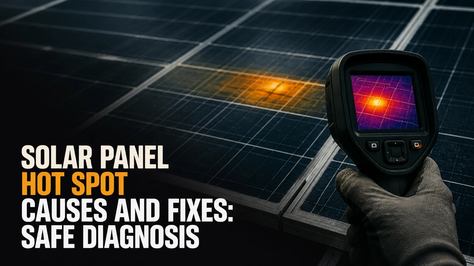
A solar panel hot spot is a localized overheated cell or electrical connection created when current becomes mismatched within a module. Common triggers include partial shading, bird droppings, cracked cells, failed solder joints, and defective bypass diodes. Cleaning can solve an external obstruction, but damaged cells, delamination, and burned junction boxes usually require professional repair or module replacement.
Key facts at a glance
A hot spot forms when a series-connected cell is forced into reverse bias and dissipates electrical power as heat.
A temperature difference alone does not prove a hot spot because wind, mounting hardware, reflections, and normal cell variation can create thermal differences.
Infrared inspection works best under strong sunlight, with the array operating and the camera set for the module surface emissivity.
A bypass diode can route current around a shaded cell group, but it cannot repair a cracked cell, burned ribbon, or delaminated encapsulant.
Module-level power electronics can reduce mismatch losses and improve monitoring, but they do not remove the physical defect inside a panel.
Never open a live solar junction box or disconnect energized DC connectors without qualified training and appropriate isolation procedures.
What Is a Solar Panel Hot Spot?
A solar panel hot spot is a small region that becomes substantially hotter than neighboring cells because that region is carrying current inefficiently. The affected area may be a whole cell, part of a cell, an interconnect ribbon, a busbar, or a junction-box component.
Solar cells in a conventional module are connected in series. The series circuit carries nearly the same current through every cell, so one restricted cell can become an electrical load rather than a generator. Healthy cells then force current through the weak cell, and the weak cell converts part of that electrical energy into heat.
A hot spot is therefore an electrical mismatch with a thermal consequence. It is not simply a panel that is warm because sunlight heats its glass.
How does a solar panel hot spot form?
A shaded or damaged cell produces less photocurrent than the surrounding cells, yet the series string continues trying to deliver current. When the cell voltage becomes negative, the cell enters reverse bias and dissipates power locally, with the hottest point often concentrated around a crack, shaded region, or resistive contact.
The approximate heating relationship is:
Heat power = reverse voltage × string current
For example, a cell forced to absorb 8 volts at 9 amperes would dissipate about 72 watts in a very small area. The exact value depends on module design and operating conditions, but the example explains why a single weak cell can reach damaging temperatures.
Bypass diodes divide many modules into protected cell groups. When a group becomes sufficiently reverse biased, its diode can conduct around that group. The diode limits damage and output loss, but the affected group temporarily stops contributing power.
What Causes Solar Panel Hot Spots?
The main solar panel hot spot causes fall into four groups: external shading or contamination, cell damage, high-resistance connections, and protection failures. The cause matters because cleaning cannot correct a fractured wafer, while replacing a diode cannot remove a chimney shadow.
| Cause | Electrical mechanism | Typical visible or thermal sign | Usual remedy |
|---|---|---|---|
| Bird droppings | Local photocurrent loss and reverse bias | Bright thermal patch under deposit | Careful cleaning and retest |
| Tree or chimney shade | Repeating current mismatch | Hot cell or diagonal pattern at shade edge | Remove obstruction or redesign |
| Microcrack | Current path interruption through fractured silicon | Narrow hot line or split-cell pattern | Module replacement |
| Poor solder joint | Local series resistance | Hot ribbon, busbar, or junction | Qualified module repair or replacement |
| Failed bypass diode | Protection path unavailable or permanently conducting | Hot junction box or inactive cell group | Technician diagnosis and diode replacement |
| Delamination | Moisture ingress and corrosion | Bubbles, whitening, brown areas | Warranty claim or replacement |
| Snow, leaves, or dust | Extended nonuniform irradiance | Shape matching obstruction | Remove obstruction, then inspect |
| Mismatch from manufacturing | Unequal current-voltage behavior | Repeated warm cell pattern | Warranty assessment or replacement |
Can dirt or shade create a hot spot?
Dirt, bird droppings, leaves, snow, and narrow shadows can create a hot spot when they cover enough active area to restrict current. A small clean shadow may reduce production without creating severe heating, while a hard-edged deposit that remains for days can create a much higher local stress.
Recurring shade deserves more attention than a one-time obstruction. A vent pipe that crosses one cell at the same hour every day can repeatedly stress the same location, especially during high irradiance and low wind. The module may look normal from the ground while the cell temperature rises during the shaded interval.
How do microcracks and solder defects differ?
Microcracks interrupt current collection through the silicon wafer, while solder defects add resistance to a conductive path. Microcracks commonly produce narrow or branching thermal features; solder defects more often produce a hot ribbon, busbar segment, or junction-box connection.
Installation handling is a frequent contributor. Walking on modules, dropping them, overtightening clamps, or supporting a panel incorrectly can create damage that remains electrically subtle until thermal cycling expands the defect. Cracks may also result from hail, transport vibration, or manufacturing stress.
How Does a Hot Spot Damage a Panel?
A persistent hot spot accelerates aging in the cell, encapsulant, backsheet, solder, and junction box. Repeated heating and cooling can expand cracks, weaken solder joints, discolor encapsulant, and permit moisture to reach conductive components.
The International Energy Agency Photovoltaic Power Systems Programme, in its 2018 review of photovoltaic reliability, identifies thermal cycling, moisture, mechanical stress, and ultraviolet exposure as major degradation stresses. Hot spots intensify the thermal component locally rather than exposing the entire module to the same temperature.
The National Renewable Energy Laboratory’s photovoltaic reliability work also treats electroluminescence, infrared thermography, and visual inspection as complementary methods because one test rarely identifies every defect. A thermal image can locate abnormal heating, but electroluminescence may better reveal inactive areas or cracks when the cause is not visible.
How hot is a dangerous hot spot?
There is no universal temperature difference that proves a dangerous hot spot. A 20-30°C difference from neighboring cells is a practical investigation trigger under comparable conditions, but wind, camera angle, surface emissivity, irradiance, and module construction can change the reading.
A local region reaching 80-120°C above its surroundings deserves immediate professional attention, especially if the array is under strong sunlight. Severe defects can damage polymer materials at lower temperatures over long periods, while brief high readings do not always identify the exact failure mode.
| Thermal observation | Interpretation | Recommended action | Confidence |
|---|---|---|---|
| 3-10°C warmer cell | Possible normal variation or mild mismatch | Repeat under stable irradiance | Low |
| 20-30°C warmer cell | Investigation threshold | Inspect visually and electrically | Moderate |
| 30-80°C warmer region | Probable abnormal resistance or shading | Arrange qualified diagnosis | High |
| 80-120°C warmer region | Severe localized heating | Isolate according to system procedure | High |
| Hot junction box | Diode, connector, or cable issue possible | Stop invasive testing and call technician | High |
These ranges are field screening values, not a universal compliance standard. IEC 62446-3 addresses outdoor infrared thermography for photovoltaic systems, but the standard does not turn one temperature number into a diagnosis for every module, climate, or camera.
How Are Solar Panel Hot Spots Diagnosed?
Solar panel hot spots are diagnosed by combining visual inspection, operating-condition checks, infrared thermography, electrical measurements, and, when necessary, I-V curve tracing or electroluminescence. The strongest diagnosis is a repeatable abnormality that matches a physical or electrical defect.
Step 1: Check the operating context
Record irradiance, wind, ambient temperature, module temperature, inverter output, and the time of day. Thermography is most useful when irradiance is generally above 600-700 W/m², the array is producing power, and neighboring modules receive comparable sunlight.
Avoid interpreting images taken immediately after cloud cover, during rapidly changing shade, or in strong gusts. Wind can cool one part of a module and create a false temperature contrast.
Step 2: Perform a visual inspection
Look for persistent bird deposits, leaves, cracked glass, browning, bubbles, yellowing, backsheet scorching, frame distortion, loose cables, and damaged connectors. Inspect the junction box from the exterior first, because melted plastic or discoloration indicates a condition that should not be handled casually.
Do not touch suspected burned components while the system is energized. Photovoltaic modules produce voltage whenever light reaches them, even when the inverter is switched off.
Step 3: Use infrared thermography correctly
Scan the module face from a consistent angle and distance, preferably with a calibrated camera and known emissivity settings. Compare the same cell position across adjacent modules and repeat the scan after removing suspected debris.
An infrared camera detects surface radiation, not internal electrical current directly. Reflections from the sky, shiny frames, wet glass, and nearby hot objects can create false bright areas, so a thermal pattern must be checked against the visual and electrical evidence.
Step 4: Test strings and I-V behavior
A qualified technician can compare string current, open-circuit voltage, operating voltage, insulation resistance, and inverter data. An I-V curve tracer can reveal steps, reduced fill factor, current limitation, or bypass-diode behavior.
A digital multimeter is not automatically safe for rooftop DC diagnosis. A typical residential string may exceed 400 volts DC, and utility-scale arrays can exceed 1,000 volts DC. Use appropriately rated instruments, arc-flash procedures, and lockout or isolation controls.
| Test method | Detects well | Main limitation | Typical field use |
|---|---|---|---|
| Visual inspection | Cracks, deposits, browning, bubbles | Misses concealed cell defects | First inspection |
| Infrared camera | Localized heating and diode patterns | Reflections and wind distort readings | Operating array survey |
| Clamp meter | String current differences | Does not locate the cell | String comparison |
| I-V tracer | Mismatch, diode behavior, fill-factor loss | Requires trained operator | Confirmation testing |
| Electroluminescence | Cracks and inactive cell areas | Usually requires controlled darkness | Warranty or lab diagnosis |
What Fixes a Solar Panel Hot Spot?
The correct fix depends on whether the heat comes from removable shading, a protection component, a resistive connection, or irreversible cell damage. Cleaning is appropriate for contamination; module replacement is usually appropriate for burned cells, extensive cracks, active delamination, or severe backsheet damage.
Clean removable obstructions safely
Clean modules during early morning, evening, or overcast conditions, when the glass is cooler. Use clean water and a soft nonabrasive brush, with low pressure and no aggressive chemical that could attack coatings or seals.
Do not use a pressure washer, razor blade, abrasive pad, or household solvent. Cold water on very hot glass can create thermal shock, and walking on a module can produce microcracks even when the glass does not visibly break.
After cleaning, repeat the visual and thermal inspection. If the same cell remains hot under similar irradiance, contamination was not the root cause.
Replace a failed bypass diode through a qualified technician
A failed bypass diode may cause a cell group to overheat or may remain permanently conductive, reducing module voltage. Diode replacement is technically possible on some junction boxes, but it requires module isolation, correct diode polarity and rating, connector control, sealing, and post-repair testing.
Opening a junction box on a rooftop is not a safe homeowner procedure. The correct replacement part must match the module manufacturer’s electrical requirements, and an incorrectly sealed box can introduce moisture damage that exceeds the original fault.
Replace the module when the cell is physically damaged
Replace rather than repair a module when thermal imaging confirms a persistent cell hotspot and inspection finds a crack, burn mark, extensive delamination, melted ribbon, damaged backsheet, or recurring insulation fault. Photovoltaic module repairs rarely restore the original weather seal and long-term reliability.
Check the product warranty before authorizing work. Photograph the serial number, defect, thermal image, inverter data, and installation context, because manufacturers commonly request evidence that separates product failure from shading, impact, or installation damage.
Do optimizers or microinverters fix hot spots?
Optimizers and microinverters manage electrical mismatch at the module or panel level, but they do not repair a defective cell. They can reduce the effect of a weak module on other modules and improve monitoring, while bypass diodes protect cell groups inside the module.
Module-level power electronics are useful when shading or module mismatch is a continuing system-design issue. They are not a substitute for replacing a module that has a hot cracked cell, corroded ribbon, or delaminated laminate.
| Option | Typical installed cost | Best use | Limitation |
|---|---|---|---|
| Cleaning | $150-$300 per residential array | Bird droppings, leaves, dust | Does not fix internal defects |
| Diode service | $150-$400 per affected module | Confirmed junction-box diode fault | Requires qualified electrical work |
| DC optimizer retrofit | $150-$350 per module | Persistent mismatch or monitoring need | Does not repair cell damage |
| Microinverter retrofit | $250-$600 per module | New module-level conversion | Roof electronics and added wiring |
| Module replacement | $350-$900 per module | Cracks, burns, delamination | May require sourcing and permit work |
Prices are typical North American residential ranges, not guarantees. Roof access, system voltage, permitting, manufacturer policy, and regional labor rates can change the final invoice substantially.
Which Repair Option Should You Choose?
The best repair is the least invasive option that removes the confirmed cause. Cleaning is the right first response for a removable obstruction, diode service fits a verified junction-box fault, and module replacement is the durable choice for cell or laminate damage.
| Confirmed condition | First choice | Expected production effect | Decision trigger |
|---|---|---|---|
| Bird dropping or leaf cover | Clean and rescan | Restores affected area | Heat disappears after cleaning |
| Repeating chimney shadow | Remove shade or redesign | Daily loss may continue | Pattern follows shadow timing |
| Failed bypass diode | Qualified diode service | Cell group may recover | Diode test confirms failure |
| Cracked silicon cell | Module replacement | Restores module reliability | Hot pattern remains after cleaning |
| Delamination or corrosion | Warranty replacement | Prevents progressive moisture damage | Bubbles or moisture path visible |
| Whole-system mismatch | Optimizer or redesign review | Improves string balance | Multiple modules show mismatch |
What should homeowners do?
Homeowners should document the symptom, check inverter production data, and arrange a professional infrared inspection rather than probing live DC wiring. A safe homeowner workflow includes photographing visible defects, noting when shade occurs, removing only accessible loose debris, and checking warranty coverage.
A single low-production day does not prove a hot spot. Compare several clear days against the inverter’s historical output, while accounting for seasonal sun angle, snow, grid curtailment, and inverter faults.
What should commercial operators do?
Commercial operators should combine annual or risk-based thermography with string-level performance analytics. Drone surveys can cover large arrays quickly, but handheld confirmation remains useful because drone altitude, wind, glare, and camera resolution affect diagnosis.
Prioritize modules with repeated thermal anomalies, abnormal current, or warranty-age concerns. A defect register containing module serial number, location, image, temperature differential, and corrective action makes recurring failures easier to track.
What should installers prevent?
Installers should prevent mechanical stress before the system operates. Follow the manufacturer’s clamp zones and torque values, avoid stepping on modules, protect connectors from standing water, and verify that cable management does not create connector tension.
Module-level electronics should be selected for site shading and monitoring objectives, not presented as a universal hotspot cure. Design cannot compensate for poor handling or a failed laminate.
Common Mistakes and Edge Cases
Why can an infrared image be misleading?
Infrared images can mislead when the camera sees reflected sky radiation, a nearby roof surface, a wet module, or a thermal shadow from mounting hardware. Low irradiance and changing cloud cover also reduce the contrast needed to identify a genuine electrical anomaly.
Require repeatability. A suspicious region that appears in the same cell position across two scans, under similar irradiance, and alongside a visual or electrical abnormality deserves escalation.
Can a bypass diode itself become hot?
Yes. A bypass diode normally conducts only when its protected cell group is sufficiently mismatched, so sustained diode heating can indicate shade, a damaged cell group, excessive current, or a diode fault. A hot junction box does not automatically prove that the diode is defective.
Thermal inspection should distinguish a warm diode from a hot cable, connector, or crimp. Each component has a different repair path.
Can a hot spot occur without visible damage?
Yes. Microcracks, hidden solder fractures, and internal delamination can produce thermal abnormalities before the glass or backsheet changes appearance. Electroluminescence and I-V testing can add evidence when visual inspection is inconclusive.
This is one reason repeated thermography is more valuable than a single casual scan. Early detection can support a warranty claim before heat causes secondary laminate damage.
How Can You Prevent Solar Panel Hot Spots?
Prevent solar panel hot spots by controlling shade, cleaning persistent contamination, handling modules without mechanical stress, and monitoring production for repeatable anomalies. Prevention also depends on selecting modules and connectors that match the system design and installation environment.
Use this maintenance schedule:
- Inspect modules visually every 6-12 months and after hail, severe wind, or nearby construction.
- Remove bird droppings and leaves when they remain over active cells rather than waiting for the next annual service.
- Check inverter alerts and monthly production against weather-adjusted expectations.
- Keep tree growth, antennas, vents, and new structures from casting recurring cell-level shade.
- Request thermography for large arrays, repeated inverter mismatch alarms, or unexplained localized production loss.
- Retain module serial numbers, installation photographs, commissioning tests, and warranty records.
A counterintuitive field rule is that a clean module can still be the failing module. Cleaning removes one cause, but it does not rule out a crack or high-resistance interconnect.
How Much Does Hot Spot Diagnosis and Repair Cost?
Typical residential diagnosis costs $200-$500 for a professional infrared survey, while corrective work ranges from approximately $150 for minor diode service to $900 for a supplied and installed replacement module. Commercial arrays usually require a site-specific quotation because access equipment, reporting, and module quantities dominate the price.
| Service | Typical price | Typical duration | Cost variable |
|---|---|---|---|
| Residential IR survey | $200-$500 | 1-3 hours | Roof access and report detail |
| String and I-V testing | $300-$1,000 | 2-6 hours | Number of strings |
| Diode diagnosis or service | $150-$400 | 1-3 hours | Junction-box access and parts |
| Optimizer installation | $150-$350 per module | 1-2 days | Permit and shutdown requirements |
| Module replacement | $350-$900 each | 1-3 hours each | Hardware, access, warranty |
| Commercial drone survey | $1,000-$5,000 | 1 day | Array size and data processing |
These figures are typical practitioner ranges rather than published universal prices. A warranty-covered module may cost little for the owner while still generating labor, shipping, lift, or administrative charges.
When Should You Shut Down the System?
Arrange urgent professional service when a module has smoke, charring, melted plastic, arcing sounds, a burning odor, exposed conductors, cracked glass with accessible electrical parts, or a hot connector. Keep people away from the equipment and follow the inverter and emergency-disconnect instructions without touching damaged DC components.
Do not spray water on an electrical fire or climb onto a roof to disconnect a damaged module. Fire departments and qualified solar electricians use site-specific procedures because modules can remain energized in daylight even after AC isolation.
FAQ
Can a small shadow really damage a solar panel?
A small shadow can reduce output without causing severe heating, but a narrow, persistent obstruction can stress the same cell repeatedly. Risk increases when the shade has a hard edge, occurs during high irradiance, and covers only part of a cell or cell group. Thermography is needed to distinguish ordinary loss from overheating.
Are solar panel hot spots covered by warranty?
Solar panel warranties may cover manufacturing defects such as failed solder joints, abnormal degradation, or defective diodes, but they often exclude impact, incorrect installation, animal damage, shading changes, and unauthorized modification. Preserve serial numbers, installation records, photographs, thermal evidence, and electrical test results before removing the module.
Can I use a phone thermal camera to find a hot spot?
A phone thermal camera can provide a screening image, but many low-cost attachments have limited resolution, uncertain calibration, and weak emissivity controls. They may locate a large hot junction box but miss a small cell defect. Use professional thermography for warranty, insurance, commercial, or safety decisions.
How long can a panel operate with a hot spot?
A panel may continue producing power for weeks, months, or years, but operating time is unpredictable because crack growth, heat cycles, moisture, and current determine the progression. Continued operation can turn a repairable diode or contamination issue into a burned laminate or fire-risk condition, so persistent hotspots should be investigated promptly.
Does replacing the bypass diode restore full panel output?
Replacing a failed bypass diode can restore normal operation when the diode caused the abnormal behavior and the cells remain intact. It cannot restore output lost to a cracked wafer, permanent shading, corrosion, or delamination. Post-repair I-V testing and thermography should confirm that the cell group now operates normally.
Conclusion: The Practical Solar Panel Hot Spot Decision
Solar panel hot spot causes and fixes are easiest to resolve when diagnosis precedes repair. Clean removable shading, confirm suspected heating with repeatable thermography, use qualified electrical testing for diode or string faults, and replace modules with cracked cells, burns, delamination, or persistent internal defects. Optimizers and microinverters can manage mismatch, but they cannot repair damaged photovoltaic cells.