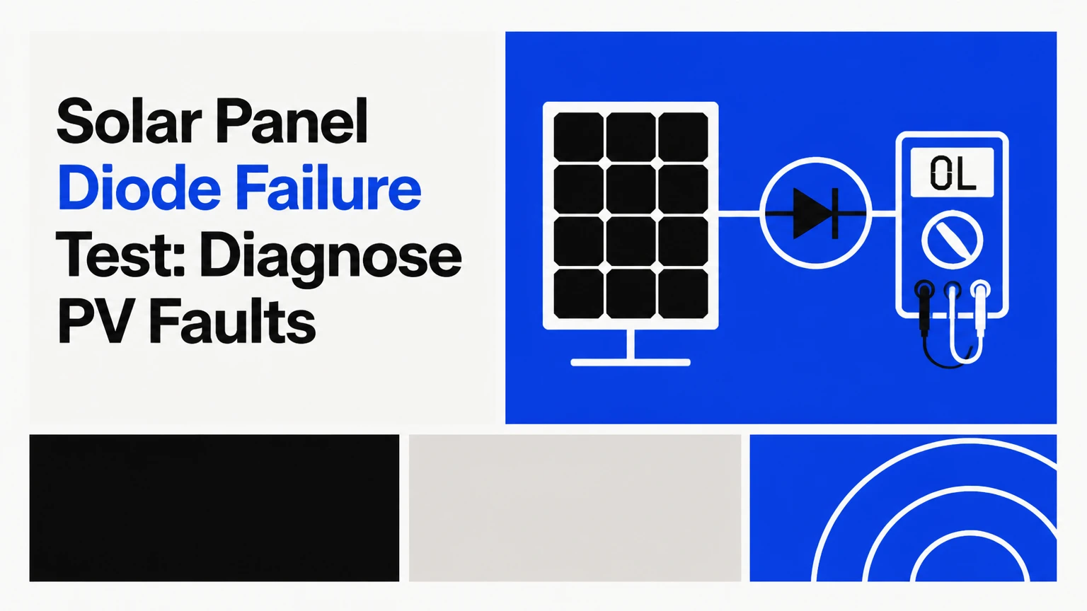
A solar panel diode failure test identifies shorted or open bypass diodes by combining module voltage, direct diode, thermal, and I-V measurements. A shorted bypass diode commonly removes one cell substring from the module voltage, while an open diode can create a dangerous hotspot when shading drives cells into reverse bias. The correct test depends on system voltage, access, irradiance, and safety controls.
Key Facts at a Glance
A healthy bypass diode conducts in one direction and blocks reverse current when tested outside the circuit.
A shorted bypass diode usually causes a module voltage loss near one substring, but module designs do not all divide into three equal sections.
A bypass diode that fails open may leave normal open-circuit voltage while producing a severe hotspot under operating current.
A DMM diode-mode test is reliable only when circuit paths do not distort the reading.
Thermal imaging and I-V curve tracing are stronger in-service methods than voltage alone.
Never disconnect MC4 connectors under load because photovoltaic DC can sustain an arc after separation.
How Does a Solar Panel Diode Failure Test Work?
A solar panel diode failure test compares electrical behavior with the module’s design data and neighboring modules under similar conditions. The test begins with non-invasive observations, then progresses to isolated voltage measurements, thermal inspection, I-V tracing, or component-level testing only when a qualified technician can safely access the junction box.
Bypass diodes sit across cell substrings, usually inside the module junction box. When one substring becomes shaded, the diode provides a lower-resistance path around that substring. Blocking diodes have a different job: they prevent reverse current into an unpowered panel or battery circuit, and they are more common in older, battery-based, or parallel-array systems.
The International Electrotechnical Commission standard IEC 62446-1 covers documentation, commissioning tests, and inspection principles for grid-connected PV systems. IEC TS 62446-3 addresses infrared thermography of photovoltaic systems and emphasizes controlled inspection conditions because irradiance, wind, reflections, and operating load affect thermal interpretation.
What Does a Shorted Bypass Diode Do?
A shorted bypass diode permanently conducts around its cell substring, reducing the module’s open-circuit voltage and maximum power. The voltage loss often resembles one-third of a conventional three-substring module, but the actual loss follows the manufacturer’s substring layout rather than a universal percentage.
For example, a module rated at 42 V open-circuit voltage might measure approximately 28 V if one of three similarly sized substrings is bypassed. A two-substring design, half-cell arrangement, or integrated electronics can produce a different signature. A 33% loss is therefore a useful screening clue, not proof.
Short failure can also create heating in the junction box because the diode carries operating current continuously. Thermal inspection should include the junction box, not only the module face.
What Does an Open Bypass Diode Do?
An open bypass diode stops current from routing around a shaded or damaged substring. The affected cells can then operate in reverse bias, dissipating power locally instead of contributing power normally. A rectangular hotspot, browned encapsulant, cracked backsheet, or melted junction-box area can result.
An open diode does not always cause a dramatic open-circuit voltage loss. During a no-load V_oc test, the diode may not need to conduct, so the module can appear electrically normal. That limitation makes operating-current thermography and I-V tracing important when heat or intermittent production loss is present.
What Should a Healthy Module Read?
A healthy isolated module should produce a voltage close to its temperature-adjusted V_oc under strong sunlight, and neighboring modules of the same model should show similar readings. A typical field comparison uses irradiance above approximately 700 W/m², but the module data sheet and measured cell temperature remain more important than a fixed sunlight threshold.
V_oc Screening Procedure
- Confirm the system state. Identify the string, module rating, maximum DC voltage, and isolation points. Record the manufacturer’s V_oc, temperature coefficient, and number of bypass diodes.
- Use qualified isolation procedures. Turn off the inverter and DC isolator where the system design permits, apply lockout procedures, and verify that the target conductors are not energized before separation.
- Measure conditions. Record irradiance, module temperature, sky condition, and the readings of at least two nearby modules.
- Measure the isolated module. Use a properly rated PV multimeter on DC voltage. Connect only after confirming polarity and a de-energized, safely isolated circuit.
- Compare the result. Compare the measured voltage with the temperature-corrected expected value and with equivalent modules tested at the same time.
- Escalate anomalies. A voltage deficit near one substring suggests a shorted bypass diode or an internal connection fault. It does not distinguish those faults conclusively.
A practical temperature correction uses the data-sheet coefficient. If V_oc is 49.5 V at 25°C and the coefficient is -0.29% per °C, a 45°C cell temperature gives an approximate V_oc of 46.6 V before other measurement effects. Use cell temperature, not ambient air temperature.
Expected Voltage Signatures
| Observation | Typical reading or pattern | Likely causes | Next test |
|---|---|---|---|
| Three-substring module, normal | 95-105% of corrected V_oc | Healthy module | I-V or thermal baseline |
| One substring bypassed | About 60-75% of corrected V_oc | Shorted bypass diode, open interconnect, substring fault | Junction-box and I-V test |
| Two substrings bypassed | About 25-45% of corrected V_oc | Two shorted diodes or multiple internal faults | Qualified component diagnosis |
| Full V_oc, low operating power | 95-105% V_oc, poor current or fill factor | Open bypass diode, shading, cracked cells, high resistance | Thermal scan and I-V curve |
| All modules read low | Similar reduction across string | High cell temperature, clouds, incorrect reference data | Repeat under stable irradiance |
| One module reads zero | 0-2 V | Open connector, fuse, cable, junction-box bond, severe internal break | Continuity and insulation diagnosis |
A module reading approximately two-thirds of expected voltage is not automatically defective. Cold-weather V_oc, inverter loading, rapid cloud movement, connector arrangement, and an incorrect nameplate comparison can all create misleading conclusions.
How Do You Test the Diode Directly?
A direct diode test requires an isolated component or a circuit design that does not place parallel PV paths across the diode. The DMM should show a forward voltage in one direction and overload, often displayed as “OL,” in reverse; exact readings vary with diode type, test current, temperature, and meter design.
Component-Level Procedure
- Remove the module from service only under an approved PV isolation procedure.
- Identify the diode’s marked cathode, normally the end with the stripe.
- Set a suitable DMM to diode mode, not resistance mode.
- Place the red lead on the anode and black lead on the cathode.
- Record the forward reading.
- Reverse the leads and record the reverse reading.
- Compare the result with the replacement diode specification and the module manufacturer’s wiring diagram.
| Diode condition | Forward direction | Reverse direction | Interpretation |
|---|---|---|---|
| Typical Schottky bypass diode | 0.15-0.45 V | OL | Normal, subject to test current |
| Typical silicon diode | 0.55-0.80 V | OL | Normal silicon behavior |
| Shorted diode | 0.00-0.10 V | 0.00-0.10 V | Conducts in both directions |
| Open diode | OL | OL | No measurable conduction |
| In-circuit ambiguous result | Variable | Variable | Parallel cells or other paths interfere |
The common mistake is treating every OL reading as proof of an open diode. A diode still connected across a cell substring can receive voltage from the cells, while other junction-box paths can create a misleading reading. If the manufacturer permits it, lift one diode lead or disconnect the relevant circuit. Do not cut, unsolder, or modify a sealed module without authorization.
How Does Thermal Imaging Find an Open Diode?
Thermal imaging finds operating abnormalities by locating a cell substring or junction box that is materially hotter than comparable areas under load. The scan works best in stable sunlight, with the inverter operating, irradiance above roughly 600-700 W/m², limited wind, and no nearby reflective surfaces.
A failed-open bypass diode often produces a localized rectangular hotspot that follows the affected substring. A shorted diode can instead appear as a hot junction-box component because the diode carries current continuously. Hotspots can also come from cracked cells, solder fatigue, soiling, partial shade, bird droppings, loose connectors, or delamination.
Thermal Inspection Rules
- Scan the module face and rear junction box when accessible.
- Record irradiance, wind speed, module temperature, camera distance, focus, and emissivity settings.
- Compare the suspect module with adjacent modules in the same string.
- Avoid interpreting a shiny frame, standing water, or reflected roof surface as a cell fault.
- Confirm a thermal anomaly with an electrical test before recommending replacement.
IEC TS 62446-3 is useful because infrared results require inspection conditions and classification, not merely a color image. A camera cannot identify the exact failed component in every case. It identifies a heat pattern that needs electrical confirmation.
Which Test Method Is Most Reliable?
I-V curve tracing is generally the strongest non-destructive confirmation method for a suspected bypass-diode fault because it measures voltage, current, maximum-power behavior, fill factor, and curve shape under operating conditions. A DMM is faster and cheaper, while thermography is faster for locating heat across many modules.
| Method | Primary target | Typical field time | Typical equipment cost | Main limitation |
|---|---|---|---|---|
| V_oc module screening | Shorted diode or open circuit | 5-15 minutes per module | $60-$250 DMM | Cannot prove an open diode |
| DMM diode mode | Shorted or open component | 20-30 minutes per accessible module | $80-$300 meter | Requires isolation and access |
| Thermal imaging | Hot substring or junction box | Under 2 minutes per module scan | $300-$6,000 camera | Needs sunlight and load |
| I-V curve tracing | Power loss and curve defects | 10-20 minutes per string | $2,500-$8,000 tracer | Requires calibration and trained operator |
| Insulation resistance test | Ground fault, not diode health | 10-20 minutes per circuit | $500-$2,000 tester | Does not identify diode condition |
An I-V curve with a step or plateau can indicate bypass-diode operation, substring loss, or mismatch. A low fill factor with normal V_oc points more toward series resistance or cell damage than a simple shorted diode. Thermal imaging should locate the anomaly, and the I-V tracer should quantify the production impact.
Why Do Solar Diodes Fail?
Solar diodes fail from thermal cycling, surge current, manufacturing defects, poor heat dissipation, reverse-voltage stress, moisture ingress, and connector or solder faults. Bypass diodes operate in harsh junction-box environments where repeated heating and cooling can fatigue solder joints and raise junction temperature.
Typical failure contributors include:
- Repeated shaded operation: A diode may carry substantial current whenever a substring is shaded.
- Lightning and switching surges: Transient overvoltage can exceed the diode’s rating.
- Undersized replacement parts: A lower-current diode can overheat even when its voltage rating appears adequate.
- Water ingress: Failed seals corrode terminals and increase resistance.
- Loose connections: A resistive termination creates local heating that can damage the diode.
- Module mismatch: Unequal current in parallel strings can increase stress on blocking components.
A practitioner rule is to inspect the connector and junction-box temperature before blaming the diode. A hot diode may be the consequence of a damaged cell substring, not the original cause.
What Safety Rules Prevent DC Arc Injuries?
PV connectors must never be separated under load. Solar modules continue producing DC whenever illuminated, and an inverter shutdown does not automatically make every module lead safe.
Use the installation manual, local electrical code, and site lockout procedure. Relevant precautions include:
- Verify the meter’s DC voltage category and maximum rating exceed the array voltage. A 1,000 V CAT III or CAT IV PV-rated instrument is typical for many systems.
- Inspect test leads, probe shrouds, fuse ratings, and connector condition before testing.
- Wear voltage-rated gloves, eye protection, arc-rated clothing, and footwear appropriate to the task.
- Cover modules or test under controlled conditions only when the procedure allows it. Covering does not replace isolation verification.
- Use DC-rated isolators and fuses rather than opening connectors as a switching method.
- Confirm zero energy with an appropriately rated meter, then verify the meter on a known source.
- Treat battery-backed off-grid systems as energized even when the PV array is isolated.
Homeowners should restrict themselves to visual inspection and data review unless a qualified electrician or solar technician has established a safe test boundary. A 600 V string can be lethal.
How Does Blocking-Diode Testing Differ?
Blocking-diode testing focuses on reverse-current prevention between a battery, charge controller, parallel string, or unpowered module. The component may be located near a controller, combiner, battery charging circuit, or older module junction box rather than across a cell substring.
With the circuit safely isolated, measure diode forward and reverse behavior as specified above. In an operating off-grid system, measure voltage drop across the blocking diode under known charging current, then compare it with the part’s current and temperature specifications. A rising drop under load suggests a resistive or thermally damaged device.
| System type | Diode commonly present | Failure symptom | Useful measurement |
|---|---|---|---|
| Grid-tied modern array | Bypass diode | Substring voltage loss or hotspot | V_oc, I-V, thermography |
| Older parallel PV array | Blocking diode | Reverse night current or string mismatch | Reverse-current and voltage-drop test |
| Battery-based controller | Blocking or MOSFET substitute | Battery discharge into array | Night current measurement |
| Combiner-fed array | String blocking device | Unequal string current | Clamp current and diode test |
Many modern charge controllers use MOSFET-based reverse-current protection instead of a conventional blocking diode. The manufacturer’s wiring diagram determines the correct diagnostic method.
Can You Repair or Replace a Failed Diode?
A bypass diode can sometimes be replaced, but repair is appropriate only when the junction box is serviceable, the module is out of warranty, and the replacement matches voltage, current, surge, temperature, package, and creepage requirements. Replacing a diode does not fix burned solder, delamination, cracked cells, or water-damaged encapsulation.
Do not pry open a potted IP-rated junction box merely to reach a diode. Breaking the seal can create a later ground fault and may void the module warranty. For a sealed or damaged junction box, document the fault with V_oc, I-V, and thermal evidence, then pursue a warranty claim or replace the module.
| Repair option | Typical time | Typical direct cost | Appropriate condition |
|---|---|---|---|
| Replace accessible diode | 20-45 minutes | $5-$30 part | Serviceable box, no cell damage |
| Replace junction box | 1-3 hours | $30-$150 part | Compatible box and qualified repair |
| Replace module | 1-2 hours | $100-$500 residential module | Sealed box, burn damage, warranty route |
| Professional diagnostic visit | 1-2 hours | $150-$350 residential | Unclear fault or high-voltage array |
| Commercial O&M investigation | 1-4 hours | $50-$150 per hour | String, block, or warranty documentation |
Typical prices vary by region, roof access, module size, and electrical labor. A replacement diode with the wrong voltage rating can fail again and can create a fire hazard.
What Are the Most Common Diagnostic Errors?
The most common diagnostic errors are testing in weak sunlight, ignoring module temperature, disconnecting energized connectors, and treating one meter reading as a complete diagnosis. Each error can produce either a false failure or an unsafe working condition.
| Error | Why it misleads | Corrective action |
|---|---|---|
| Testing under moving clouds | V_oc and current change rapidly | Repeat under stable irradiance |
| Comparing hot module to cold label value | Temperature lowers V_oc | Apply the coefficient and measure cell temperature |
| Testing a diode in circuit | PV substrings create parallel paths | Isolate or lift one lead when authorized |
| Using resistance mode only | Meter current may be insufficient | Use diode mode and component data |
| Opening MC4 connectors under load | DC arc can persist across contacts | Isolate, verify, then disconnect |
| Reading a thermal image alone | Reflections and shade mimic heat | Confirm with electrical measurements |
An expert rule of thumb is to compare same-model modules at the same time, not a suspect module against a nameplate alone. Relative comparison often reveals a fault faster than absolute specification matching.
How Long Does Testing Take?
A basic module voltage screen takes approximately 5-15 minutes per module after safe access and isolation are established. A thermal scan can take less than two minutes per module, while a component-level junction-box test commonly requires 20-30 minutes and may require module removal.
| Task | Typical duration | String downtime | Best use |
|---|---|---|---|
| Visual inspection and records | 15-30 minutes per string | None | First triage |
| Thermal scan | 1-2 minutes per module | None if safely observed in operation | Locate hotspots |
| Isolated V_oc test | 5-15 minutes per module | Target string or module | Screen voltage loss |
| I-V curve trace | 10-20 minutes per string | Usually brief | Quantify power defect |
| Junction-box test | 20-30 minutes per module | Full module isolation | Confirm component failure |
A residential service visit typically lasts one to two hours when roof access is straightforward. Utility-scale surveys may scan thousands of modules per day, but every flagged location still needs ground-level validation.
Which Method Should You Choose?
Choose V_oc screening for a quick indication of a shorted bypass diode, thermal imaging for operating hotspots, direct diode mode for an accessible component, and I-V tracing for documented performance diagnosis. No single test reliably identifies every bypass-diode failure.
- Homeowner with a low-production alert: Contact the installer and provide inverter logs, photos, and professional test results. Avoid opening the junction box.
- Installer with one low-voltage module: Compare corrected V_oc readings, inspect connectors, then perform thermal or I-V confirmation.
- Off-grid owner with nighttime battery drain: Investigate blocking or controller reverse-current protection rather than assuming a bypass diode failed.
- Commercial operator with many anomalies: Use aerial or handheld thermography for triage, followed by I-V tracing and targeted electrical tests.
- Warranty claimant: Preserve serial numbers, data sheets, irradiance records, temperature readings, thermal images, and curve traces.
The least expensive test is not always the best first test. If a hotspot is visible, operating thermography can prevent unnecessary module disassembly.
Frequently Asked Questions
Can a bad bypass diode cause low voltage but normal current?
Yes. A shorted bypass diode can remove one cell substring from the module voltage while the remaining active substrings still carry current close to the string operating current. The module’s power then falls because voltage decreases, although current may look normal during a basic clamp-meter check.
Can shade damage a bypass diode?
Shade does not automatically damage a bypass diode, but persistent partial shading can force the diode to carry current and heat repeatedly. Poor ventilation, high ambient temperature, surge events, and an undersized diode increase stress. Shade from a chimney or tree should therefore be assessed alongside diode temperature and module design.
What does a solar panel diode failure test cost?
Typical residential diagnostic service costs $150-$350, while a basic 1,000 V PV-rated multimeter costs approximately $60-$250. Thermal cameras range from about $300 for entry-level attachments to several thousand dollars for professional equipment, and commercial I-V tracers commonly cost $2,500-$8,000.
Can an insulation-resistance test find a bad bypass diode?
An insulation-resistance test can identify leakage to frame or ground, but it does not reliably identify a shorted or open bypass diode. The test addresses insulation integrity, while diode mode, V_oc, thermography, and I-V tracing address diode and substring behavior.
Should a module with a failed diode be replaced?
Replace the module when the junction box is potted, burned, water-damaged, or under warranty, or when cell damage remains after diode replacement. A qualified technician may replace an accessible diode when the box, wiring, backsheet, and cells remain sound and the replacement part meets the original specification.
The Bottom Line
A solar panel diode failure test should begin with safe visual inspection and corrected V_oc comparison, then use thermal imaging or I-V tracing to confirm how the module behaves under load. Direct DMM testing can verify an accessible diode, but it is unreliable through parallel PV paths and unsafe when isolation is incomplete. Document the fault before repairing or replacing the module.