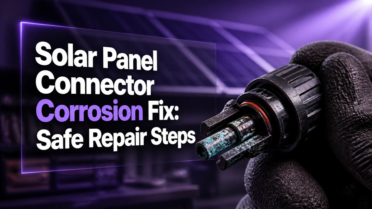
A solar panel connector corrosion fix usually means replacing the affected connector, not merely washing its contacts. Disconnect the photovoltaic system only under qualified supervision, inspect for heat or water damage, and replace any pitted, loose, discolored, melted, or cross-mated connector with a manufacturer-approved matching pair.
Key facts at a glance
A warm, browned, cracked, melted, or arc-marked PV connector requires replacement rather than cleaning.
A photovoltaic connector must match the cable size, voltage rating, current rating, sealing system, and approved mating connector.
Never disconnect an energized solar connector because a DC arc can continue after the contacts separate.
IP67 or IP68 describes the connector’s tested enclosure rating, not an incorrectly assembled field connection.
Dielectric grease is not automatically suitable for PV contacts; follow the connector manufacturer’s instructions and keep unapproved grease away from mating metal surfaces.
A correct repair requires a solar-rated cable stripper, connector-specific crimp die, assembly tools, and a verified mechanical pull test.
What Causes Solar Connector Corrosion?
Solar connector corrosion begins when moisture reaches the conductive contact or crimp area. Failed seals, incomplete insertion, damaged cable jackets, loose gland nuts, condensation, contamination, and incompatible connector halves can all create a path for water and oxygen.
Salt spray accelerates corrosion on coastal arrays because dissolved salts increase surface conductivity and leave chloride contamination behind after water evaporates. Agricultural chemicals, industrial pollutants, bird droppings, and trapped dirt can produce similar contamination in other environments.
The visible green or white deposit is only part of the problem. Corrosion can reduce the real contact area, increase resistance, weaken the spring force of a socket, and damage plating. Current through that resistance produces heat according to the relationship (P=I^2R), so a small resistance increase becomes more serious at high string current.
A connector can therefore look acceptable while heating under load. Thermal cycling then changes the fit between the male and female contacts, which can accelerate fretting and electrical arcing.
What Does Corrosion Look Like?
| Inspection finding | Likely condition | Repair decision | Typical urgency |
|---|---|---|---|
| Light dull film on clean, cool contact | Surface tarnish | Qualified inspection and possible cleaning | Same maintenance visit |
| Green or white powder inside housing | Moisture-driven corrosion | Replace connector pair and inspect cable | Prompt |
| Brown plastic or black arc mark | Overheating or arcing | Replace connector and investigate cause | Immediate shutdown by qualified person |
| Melted locking tabs or distorted shell | Thermal damage | Replace connector pair | Immediate |
| Water droplets or wet seal | Ingress or condensation | Replace seal or connector, inspect cable | Prompt |
| Loose terminal in housing | Failed retention or crimp | Re-terminate with approved connector | Prompt |
Is Cleaning or Replacement the Right Fix?
Replacement is the correct fix when corrosion has caused pitting, looseness, heat discoloration, arc damage, seal failure, or plastic deformation. Cleaning is limited to minor surface contamination on a mechanically sound connector, and even that work should follow the connector manufacturer’s service instructions.
| Condition | Clean? | Replace? | Reason |
|---|---|---|---|
| Contact remains smooth and plated | Possibly | If manufacturer requires | Surface residue may be removable |
| Contact is pitted or deeply stained | No | Yes | Lost plating and reduced contact area remain |
| Housing is warm or discolored | No | Yes | Heat damage cannot be reversed with solvent |
| O-ring is cut, flattened, or missing | No | Yes or approved seal kit | Water protection is compromised |
| Connector halves are different brands | No | Yes | Mechanical compatibility is not established |
| Cable insulation is cracked | No | Yes, including cable section | Moisture can travel through damaged insulation |
| Locking mechanism works and no heat exists | Possibly | Not necessarily | Mechanical integrity may remain |
A practitioner rule is simple: corrosion is a cleaning problem only when the metal, plastic, seal, crimp, and locking mechanism are all intact. A contact that has overheated must not be returned to service because polishing it can remove more plating and conceal the failure.
Why Does a Hot Connector Need Replacement?
A hot PV connector indicates abnormal resistance, a poor crimp, incomplete insertion, contamination, or incompatible mating parts. Replacing the housing alone may leave a damaged cable crimp or overheated contact in service, so the repair should normally remove the connector and a short section of affected cable.
Infrared inspection is useful while the array is producing substantial current, but temperature alone does not prove the fault location. Compare equivalent connectors in the same string and inspect the cable crimp after isolation. A professional may also measure voltage drop across the connection under load, because an open-circuit resistance test can miss a fault that appears only when current flows.
How Do You Diagnose a Corroded PV Connector?
Diagnosis starts with visual inspection and system comparison, followed by qualified electrical testing. Do not separate connectors for testing while the circuit is energized, and do not assume that an inverter shutdown removes voltage from every exposed conductor.
| Symptom | Best verification | Possible cause | Corrective action |
|---|---|---|---|
| String output is lower than comparable strings | Inverter string data and irradiance comparison | High-resistance connector, module fault, shading | Isolate and test professionally |
| Inverter reports arc-fault code | Event log, visual inspection, insulation testing | Loose crimp, damaged connector, cable fault | Stop repeated resets and inspect |
| Connector is hotter than adjacent connectors | Thermal camera under load | Contact resistance or loose crimp | Replace connector and inspect termination |
| Intermittent production after rain | Weather-linked monitoring | Water ingress or condensation | Replace damaged seal or connector |
| Open circuit voltage is normal but power is low | Loaded voltage-drop test | High-resistance connection | Repair termination |
| Connector separates or will not lock | Mechanical inspection | Broken latch or incorrect pair | Replace with approved matching pair |
A digital multimeter is not a substitute for safe isolation procedures. A photovoltaic string may exceed 1,000 V DC, and parallel strings can backfeed current even after one circuit is opened. Local electrical rules, inverter instructions, and the connector manufacturer’s procedures control the shutdown sequence.
Before You Start the Repair
A connector replacement normally takes 15-30 minutes after safe isolation, but rooftop access, multiple strings, damaged cable, and verification can extend professional work to 1-3 hours. The determining factor is not crimp speed; it is whether the entire circuit can be made dead and verified by a competent person.
| Requirement | Typical value or specification | Why it matters |
|---|---|---|
| PV cable | 4 mm² or 6 mm², 1,000 V or 1,500 V DC | Connector barrel must match conductor size |
| Replacement connector | Same manufacturer and approved mating model | Prevents dimensional and sealing mismatch |
| Connector rating | Equal to or above system voltage and current | Lowest-rated component controls safety |
| Strip length | Manufacturer-specified, commonly 6-8 mm | Incorrect length causes weak crimp or exposed conductor |
| Crimp tool | Connector-specific ratcheting tool | Correct die profile controls contact resistance |
| Assembly wrench | Connector-specific pair | Prevents gland under-torque or housing damage |
| Inspection tools | Flashlight, magnifier, thermal camera if available | Finds heat, pitting, and seal faults |
| Personal protection | Arc-rated and electrical PPE selected by qualified worker | Reduces shock and arc-flash risk |
Do not use ordinary pliers as a crimper. Do not improvise a replacement with a household electrical terminal. PV cable, connector, crimp profile, and sealing gland form one tested assembly.
Stäubli installation documentation states, “Do not disconnect under load.” That short instruction is the central safety rule for MC4-type photovoltaic connectors. A homeowner who cannot verify a de-energized, isolated circuit should stop at visual inspection and call a solar electrician.
Step-by-Step: Replace a Corroded Solar Connector
Step 1: Identify the connector and cable
Record the connector manufacturer, model, cable cross-section, system voltage, and connector polarity before ordering parts. Photograph the installed orientation, because connector shell gender and electrical polarity are separate details.
Use an identical approved connector pair whenever possible. “MC4-compatible” is a marketing description, not proof that two brands have been tested together.
Success checkpoint: The replacement part number, cable size, voltage rating, and current rating all match the installation requirements.
Common mistake: Ordering a connector based only on the appearance of the plastic shell.
Step 2: Isolate and verify the circuit
Follow the system shutdown sequence from the inverter, DC disconnect, rapid-shutdown equipment, and local electrical code. A qualified person must test for zero voltage at the intended work point with an appropriately rated meter, including possible backfeed from parallel strings.
Do not work during rain, condensation, or wet conditions. Disconnecting a live DC connector can sustain an arc that damages contacts and ignites nearby material.
Success checkpoint: The responsible qualified worker confirms the circuit is isolated and voltage-free at the repair location.
Common mistake: Treating an inverter display that says “off” as proof that the panel-side conductors are dead.
Step 3: Cut out the damaged connector
Cut the cable cleanly 50-100 mm behind the damaged housing, or farther if heat has traveled into the insulation. Inspect the remaining jacket for browning, hardening, cracks, flattening, and moisture migration.
If insufficient cable remains for the manufacturer’s termination length, install an approved solar-rated junction method or have the cable section replaced. Do not stretch a short cable to place mechanical load on the new connector.
Success checkpoint: The remaining cable has flexible, undamaged insulation and clean copper strands.
Common mistake: Reusing cable that looks normal externally but has brittle insulation immediately behind a melted connector.
Step 4: Install the gland components
Place the replacement connector’s gland nut and sealing insert on the cable before attaching the contact. Follow the connector assembly order exactly, because reversing the seal can prevent correct compression.
Keep the cable dry and free from grit. Do not apply household silicone, thread sealant, petroleum jelly, or random grease unless the connector manufacturer specifically approves the product and location.
Success checkpoint: The gland, seal, and nut sit in the correct order without cuts, twists, or contamination.
Common mistake: Crimping the terminal first and discovering that the gland nut cannot pass over it.
Step 5: Strip and crimp the cable
Strip only the length specified by the connector maker, commonly 6-8 mm for many MC4-style products. Do not nick strands, twist them excessively, solder the conductor, or remove jacket beyond the sealing zone.
Insert the conductor fully into the terminal barrel and crimp it with the specified die and ratcheting tool. Perform a firm manual pull test after the tool releases. A pull test does not replace a calibrated crimp standard, but it catches an incompletely inserted conductor.
Success checkpoint: No bare copper extends beyond the terminal, the crimp is symmetrical, and the conductor does not move under a firm pull.
Common mistake: Using the wrong die for a 4 mm² terminal on 6 mm² cable, producing a loose or crushed connection.
Step 6: Insert the contact into the housing
Push the crimped contact into the correct connector shell from the rear until the retention feature locks. Confirm the contact cannot pull back and that the housing’s keying matches the intended mating half.
Connector shell gender can confuse installers: the visible housing shape does not always indicate whether the internal conductive contact is a pin or socket. Use the manufacturer’s assembly diagram rather than relying on appearance.
Success checkpoint: The contact is fully seated, retained, and aligned with the connector’s keying.
Common mistake: Forcing a contact into the wrong shell and damaging the retention fingers.
Step 7: Tighten the cable gland
Hand-start the gland nut to avoid cross-threading, then tighten it with the manufacturer’s specified assembly tool and torque. Published values differ by connector design, cable diameter, and seal type, so there is no universal MC4 torque value.
The gland should compress the cable without cutting the jacket. Do not compensate for a wrong cable diameter by overtightening the nut.
Success checkpoint: The nut reaches the specified position or torque, the cable has strain relief, and the seal is evenly compressed.
Common mistake: Leaving the nut hand-tight because the connector feels mechanically secure.
Step 8: Mate, inspect, and document
Mate the approved connector halves until the locking mechanism engages. Inspect the seam, latch, cable entry, and orientation, then secure the cable to the racking with UV-rated clips so its weight does not hang from the connector.
After the system is re-energized by the qualified worker, compare string current and connector temperature with equivalent circuits under similar irradiance. Record the connector model, repair date, cable size, and test results.
Success checkpoint: The connector is fully locked, supported, dry, and electrically normal under load.
Common mistake: Leaving the repaired connection resting on the roof where standing water, abrasion, or cable tension can recur.
Can a Lightly Oxidized Connector Be Cleaned?
A lightly oxidized connector may be serviceable only when the contact remains smooth, the plating is intact, the housing is undamaged, and the manufacturer permits cleaning. Remove the connector from service, isolate it safely, use an approved electrical contact cleaner sparingly, and allow every component to dry fully before inspection.
Do not use a wire brush, file, sandpaper, carburetor cleaner, or aggressive solvent on plated PV contacts unless the manufacturer explicitly specifies it. Abrasion can remove the conductive plating, while solvent residue can attack seals or plastic. Cleaning cannot restore spring tension, fill pits, repair an arc crater, or rebuild a failed crimp.
A safe field decision table is more useful than a universal solvent recommendation.
| Cleaning method | Suitable use | Main risk | Field position |
|---|---|---|---|
| Manufacturer-approved contact cleaner | Light surface film on intact metal | Seal or plastic incompatibility | Use only after approval |
| Lint-free wipe | Loose dry contamination | Leaves oxide behind | Low-risk first action |
| High-purity isopropyl alcohol | Compatible external residue removal | Incomplete drying | Confirm material compatibility |
| Wire brush or abrasive | None for plated PV contacts | Removes plating and creates scratches | Avoid |
| Household lubricant | None | Contaminates seal and contact | Avoid |
| Silicone dielectric grease | Seal treatment only if approved | Insulates or traps contamination on contact | Keep off mating surfaces |
Should You Apply Dielectric Grease?
Dielectric grease should not be packed onto the conductive mating surfaces of a PV connector unless the connector manufacturer expressly approves that application. Some manufacturers specify a particular grease, while others rely on the contact design and prohibit additional compounds; the connector manual controls.
If approved, a very thin film may be placed on an O-ring or designated seal surface, not used to hide corrosion or compensate for a damaged gland. Conductive anti-oxidant compounds are also not interchangeable with dielectric grease, and a product designed for building-service aluminum terminals may be unsuitable for a PV connector’s plating or elastomer.
The counterintuitive point is that more grease does not create a better electrical connection. Excess compound can migrate, collect grit, interfere with contact pressure, and make later inspection harder.
Which Connector Specifications Matter?
The replacement connector must meet or exceed the system’s electrical and environmental requirements, but ratings must be read as a complete assembly. A 1,500 V connector does not make a 1,000 V cable, undersized crimp, or incompatible mating pair safe.
| Specification | Common PV values | Selection rule |
|---|---|---|
| Maximum system voltage | 1,000 V DC or 1,500 V DC | Equal to or above array maximum voltage |
| Rated current | 20 A, 30 A, 40 A, or 50 A | Equal to or above design current |
| Cable size | 4 mm², 6 mm², or 10 mm² | Must match terminal barrel and seal |
| Ingress protection | IP67 or IP68 | Requires correct assembly and mating |
| Operating temperature | Approximately -40°C to +85°C or +90°C | Use the exact product datasheet |
| Contact resistance | Manufacturer-specific, often below 1 mΩ when new | Compare like-for-like test conditions |
| Certification | UL, TÜV, IEC, or regional approval | Match project and jurisdiction requirements |
Connector ratings are not interchangeable across brands. A genuine Stäubli connector, an Amphenol connector, and a generic connector may use similar shapes while having different contact geometry, sealing dimensions, crimp tooling, and certification conditions.
What Are the Most Common Repair Errors?
| Error | Result | Recovery |
|---|---|---|
| Mixing connector manufacturers | Poor fit, water ingress, heating | Replace both mating halves with one approved pair |
| Crimping with pliers | High-resistance or weak termination | Cut off and re-terminate with correct die |
| Reusing a heat-damaged contact | Repeat hotspot or arc fault | Replace the connector and affected cable |
| Over-tightening the gland | Cut jacket or distorted seal | Replace damaged seal and torque correctly |
| Leaving cable unsupported | Repeated seal and crimp stress | Add UV-rated clips and correct cable routing |
| Resetting arc-fault alarms repeatedly | Continued heating and fire risk | Isolate system and investigate the circuit |
One practitioner rule prevents many failures: never repair only the symptom that is easiest to see. A melted shell usually represents a thermal event at the contact or crimp, so inspect the terminal, conductor strands, cable insulation, mating connector, and string operating conditions.
Another rule concerns connector age. A five-year-old connector is not automatically defective, and a new connector is not automatically reliable. Installation quality, environment, current, mating compatibility, and water exposure matter more than calendar age.
How Much Does Connector Repair Cost?
Typical material cost is $10-$30 for a certified replacement pair, while professional service commonly costs $150-$350 for diagnosis and access, plus approximately $20-$75 per connector depending on location and cable work. Rooftop access, rapid-shutdown equipment, multiple damaged connectors, and corrective rewiring increase the final price.
| Repair scope | Typical materials | Typical labor time | Typical total cost |
|---|---|---|---|
| Inspection only | $0-$50 | 30-90 minutes | $100-$300 |
| One accessible connector | $10-$30 | 30-60 minutes | $150-$350 |
| Four rooftop replacements | $40-$120 | 1.5-3 hours | $300-$800 |
| Cable section and connector repair | $30-$150 | 2-4 hours | $400-$1,000 |
| Commercial array investigation | $100-$500 testing | 2-8 hours | $500-$2,000+ |
Prices vary by country, roof access, licensing requirements, and whether the fault affects a single connector or an entire installation batch. A low connector price does not justify using an uncertified clone in a high-voltage string.
How Do Coastal and Mobile Systems Change the Repair?
Coastal systems need more frequent inspection because salt deposits, humidity, and wind-driven water accelerate contamination and seal stress. RV and portable systems experience additional vibration, repeated mating cycles, cable bending, and connector impact, so strain relief and mechanical inspection deserve greater attention.
| Installation situation | Added exposure | Inspection focus | Practical interval |
|---|---|---|---|
| Coastal rooftop | Salt spray and high humidity | White deposits, seals, cable clips | Every 6-12 months |
| Inland residential roof | UV, rain, thermal cycling | Heat marks and loose routing | Annually |
| Desert array | Dust, UV, large temperature swings | Glands, brittle seals, abrasion | Every 6-12 months |
| RV or trailer | Vibration and repeated movement | Locking tabs and cable strain | Before each major trip |
| Agricultural site | Fertilizer and chemical contamination | Housing residue and seals | Every 6-12 months |
| Commercial utility array | High connector count and load | Thermal survey and batch patterns | Scheduled O&M program |
These intervals are typical maintenance guidance, not a substitute for the equipment owner’s manual or site risk assessment. A thermal anomaly or arc-fault alarm overrides the calendar.
FAQ
Can I replace only one half of an MC4 connector?
Replace the damaged connector with the manufacturer-approved mating half, and replace both halves when the original pair is mixed-brand, heat-damaged, corroded, or unknown. Pairing a new connector with a visibly sound but incompatible half can preserve the mechanical and sealing fault that caused the original failure.
How can I tell whether a solar connector is compatible?
Check the manufacturer, exact model, cable diameter, voltage rating, current rating, certification, and approved mating list. Similar housing shapes are insufficient evidence. If the connector brand or model cannot be identified, a qualified installer should replace the complete connector pair with a documented, certified system.
Can rain cause a solar connector to fail immediately?
Rain can expose an existing sealing or assembly defect, but corrosion usually develops over repeated moisture cycles rather than in one event. Water inside the housing, a loose gland, an incomplete latch, or a damaged O-ring requires prompt isolation and inspection because the connector may heat when current returns.
Is a low string voltage proof that the connector is corroded?
Low string voltage does not prove connector corrosion. Shading, a failed module, an open bypass diode, insulation damage, an inverter issue, or a disconnected connector can produce similar readings. Compare open-circuit voltage, operating current, monitoring data, and qualified loaded voltage-drop tests before selecting the repair.
How often should PV connectors be inspected?
Inspect residential connectors at least annually and after severe weather, while coastal, agricultural, desert, RV, and commercial systems may need six-month or event-based checks. Inspect immediately after an arc-fault alarm, unexplained string loss, visible water ingress, or a connector that feels warmer than adjacent connections.
Does a solar connector corrosion fix restore lost power automatically?
A correct solar panel connector corrosion fix restores the electrical path only if the connector caused the loss and no module, cable, fuse, or inverter fault remains. After replacement, verify string voltage, operating current, monitoring data, connector temperature, cable support, and alarm status under normal sunlight.
The Bottom Line
The safest solar panel connector corrosion fix is replacement when the connector shows heat, pitting, looseness, seal damage, mixed-brand mating, or plastic deformation. Cleaning is a narrow option for light surface contamination on an otherwise intact connector, and high-voltage DC isolation, connector compatibility, correct crimping, gland torque, and post-repair verification determine whether the repair remains safe.