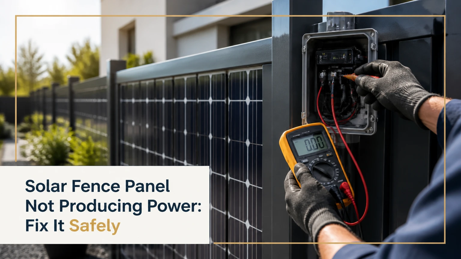
A solar fence panel not producing power may have a shading, connector, wiring, inverter, monitoring, or panel fault. Start by confirming whether the entire system is offline or only one module is underperforming, then inspect the site and inverter before any electrical testing. Live photovoltaic DC circuits can remain energized in daylight, so qualified personnel should perform voltage, current, insulation, and connector tests.
Key Facts at a Glance
- A single shaded or damaged module can reduce the output of a series string, especially when panels share one MPPT input.
- A zero reading in an app does not prove that the fence panel is defective because communications and inverter faults can hide normal DC production.
- Vertical solar panels usually produce less annual energy than optimally tilted panels at the same location, although they can produce more evenly during morning and afternoon hours.
- Bifacial modules need rear-side light and clearance; a panel pressed against an opaque fence cannot receive a meaningful bifacial gain.
- Do not disconnect MC4 connectors under load or place a household multimeter directly across a live panel to measure short-circuit current.
- A replacement panel must match electrical characteristics, connector compatibility, dimensions, fire classification, and the inverter’s permitted voltage range.
What Counts as a Solar Fence Panel?
A solar fence panel is a photovoltaic module used as, attached to, or integrated into a property boundary. The phrase covers glass-on-glass bifacial modules between posts, ordinary framed modules mounted to a fence, and building-integrated photovoltaic pickets or composite sections.
The photovoltaic cells convert light into direct-current electricity. A string inverter or microinverter then converts DC into grid-compatible alternating current, while a monitoring gateway reports production. The panel itself does not produce household AC power, and a panel can show voltage even when the inverter is refusing to export electricity.
Solar fence systems have several architectures:
| System architecture | Typical module rating | Electrical arrangement | Common failure scope |
|---|---|---|---|
| Bifacial glass module | 350-550 W | Series string or optimizers | One module, string, or rear shading |
| Monofacial framed module | 300-450 W | Series string or microinverter | Front shading, connector, module |
| BIPV fence section | 100-350 W per section | Proprietary DC harness | Section electronics or controller |
| Solar picket system | 20-150 W per picket | Parallel low-voltage bus | Individual picket or shared bus |
A fence panel is not automatically a specialized solar product. Many installations use standard modules with custom posts, rails, conduit, and protective barriers. The replacement process therefore depends on the module label and system design, not on the fence appearance.
How Does a Solar Fence Generate Electricity?
A solar fence module generates DC power when cell irradiance is sufficient, but the inverter determines whether that power becomes usable AC output. The inverter searches for the array’s maximum power point, checks grid and insulation conditions, and disconnects when voltage, frequency, or safety limits are outside specification.
The basic path is:
- Photovoltaic cells produce DC voltage and current.
- Modules connect into strings or to individual microinverters.
- An MPPT controller selects an operating voltage.
- The inverter converts DC to AC.
- The meter, gateway, or utility connection records export or consumption.
Vertical orientation changes the daily production curve. In the Northern Hemisphere, a south-facing vertical plane receives useful midday sun, while east-west arrangements can divide morning and afternoon production. A north-facing monofacial panel generally performs poorly in the Northern Hemisphere, but reflected light, local latitude, seasonal sun angles, and bifacial construction affect the actual result.
NREL’s PVWatts model treats orientation, tilt, shading, temperature, and system losses as separate production inputs. That distinction matters: a fence can be electrically healthy yet produce less than a rooftop array because its plane receives less annual irradiance.
Why Does Vertical Orientation Matter?
Vertical photovoltaic fencing usually sacrifices some noon production compared with a 30-45-degree roof array, but it can gain useful morning, afternoon, or winter exposure. Vertical panels also shed snow more readily than low-slope panels, although ice, mud, salt spray, and vegetation can still reduce output.
Bifacial gain is conditional, not guaranteed. A light concrete surface may reflect more usable light than dark soil, but a tightly enclosed panel with an opaque rear surface receives little rear irradiance. The installer should model the actual fence spacing rather than apply a blanket 25% gain.
What Failed: Panel, String, Inverter, or Monitoring?
The first diagnostic question is whether production is absent physically or only absent from the monitoring display. Compare the inverter’s local display, utility meter, gateway status, and historical production before opening a connector or panel junction box.
| Observed symptom | Most likely area | Safe first check | Typical next action |
|---|---|---|---|
| Whole array reads zero | Inverter, AC supply, grid, shutdown | Inverter display and AC status | Installer checks inverter and breakers |
| One string is low | String fuse, connector, shading, module | Compare string history | Qualified DC testing |
| One module is low | Module, optimizer, microinverter, shade | Visual inspection and app data | Warranty or installer diagnosis |
| App is blank, inverter is normal | Gateway, Wi-Fi, cellular link | Local inverter production | Restore communications |
| Output falls at midday | Heat, shade, clipping, loose connection | Shade timeline and temperature | Thermal and electrical inspection |
| Inverter repeatedly restarts | Grid, insulation, arc fault, DC interruption | Record exact code | Keep system isolated and call service |
A string inverter can make one weak module appear to be a whole-string problem. Microinverters usually localize the fault to one module, but a failed communications gateway can make many healthy microinverters appear inactive.
How Should You Troubleshoot a Nonproducing Fence Panel?
Use a staged process that begins with observation and ends with qualified electrical measurements. The sequence below minimizes unnecessary disconnections and preserves evidence for a warranty claim.
Step 1: Confirm the Production Baseline
Record the date, time, weather, inverter status, array power, and the affected panel or fence section. Compare the same hour with a clear day from the previous month, adjusting for season and cloud cover.
A cloudy day cannot establish a panel failure. A clear day with the entire array at zero can establish a system-level problem more reliably than a single low app reading.
Success checkpoint: the inverter, monitoring portal, and utility meter tell a consistent story.
Common mistake: comparing winter vertical-fence output with summer rooftop output without accounting for solar angle and day length.
Step 2: Inspect Shade and the Fence Surface
Look for new tree branches, parked vehicles, gates, vines, tall grass, privacy screens, snow, mud, bird deposits, and nearby construction. Photograph shadows at morning, solar noon, and late afternoon because a vertical fence may be shaded during the exact period when it normally generates.
Inspect glass, laminate, frames, posts, and cable entries from ground level. Cracks, cloudy delamination, browning, bubbles, burn marks, and water inside a connector justify service rather than cosmetic cleaning.
Success checkpoint: the panel has an unobstructed front face, usable rear clearance if bifacial, and no visible damage.
Common mistake: trimming vegetation or washing glass while standing near exposed conductors or damaged modules.
Step 3: Read the Inverter and Microinverter Status
Photograph every error code and indicator pattern before resetting anything. Common categories include grid overvoltage, grid undervoltage, isolation resistance, arc-fault detection, DC overvoltage, ground fault, temperature, and communication failure.
A green indicator does not always mean every panel is producing. Some inverters display only that the AC side is connected, while a portal may report stale data. A reset can erase useful fault timing, so document first and follow the manufacturer’s restart procedure.
Success checkpoint: the exact model, code, timestamp, and affected input are recorded.
Common mistake: repeatedly cycling DC and AC disconnects without waiting the manufacturer-specified discharge period.
Step 4: Check Accessible, Deenergized Connections
Only inspect connectors that can be reached without removing covers or entering the electrical enclosure. Look for partially seated locking tabs, pulled cables, sharp bends, rodent damage, crushed conduit, corrosion, and water tracking near fence posts.
MC4-style connectors must be the correct mating type and properly assembled. Mixing visually similar connectors from different manufacturers can create resistance, heat, and arcing even when the pieces click together.
Success checkpoint: cables have strain relief, connectors are dry and fully engaged, and no connector is resting in standing water.
Common mistake: disconnecting photovoltaic connectors in sunlight, which can create an arc and damage the contacts.
Step 5: Have a Qualified Technician Test the DC Circuit
A technician should use photovoltaic-rated instruments and follow IEC 62446-1 commissioning and verification practices. Appropriate tests can include open-circuit voltage, operating current, polarity, insulation resistance, continuity of protective conductors, and, where needed, I-V curve tracing.
The measured value must be compared with the module datasheet at the measured irradiance and temperature. A panel’s nameplate short-circuit current is a laboratory rating, not a value it must reach under every outdoor condition.
Success checkpoint: the technician identifies whether the abnormality is at module, connector, string, inverter input, or grounding level.
Common mistake: placing a standard multimeter in current mode directly across a live module, which can blow the meter fuse, damage the panel circuit, or create an arc.
Step 6: Test Bypass Diodes Only as a Repair Diagnosis
Bypass diodes protect shaded cell substrings from excessive reverse bias. A failed diode can cause low voltage, abnormal heating, or reduced power, but diode access often requires opening the junction box and can void the module warranty.
Thermal imaging under load can reveal a hot diode, connector, or cell region before invasive work. The technician should isolate the module, verify the absence of hazardous voltage, and follow the module maker’s repair instructions.
Success checkpoint: the diode or junction-box fault is confirmed by an approved procedure, not inferred from a low app value.
Common mistake: replacing a diode without identifying why the original overheated, such as shading, a high-resistance connection, or water entry.
Which Fault Matches Your Symptoms?
A symptom matrix prevents a common diagnostic error: replacing the panel when the inverter or communications system is the actual cause.
| Fault type | Electrical clue | Physical clue | Recommended response |
|---|---|---|---|
| Partial shade | Current falls while voltage remains plausible | Predictable shadow pattern | Remove obstruction or redesign |
| Open connector | String voltage is absent or intermittent | Loose lock, corrosion, pulled cable | Qualified connector replacement |
| Shorted bypass diode | Reduced module voltage | Local hot spot possible | Module or junction-box service |
| Broken cell interconnect | Low current or unstable I-V curve | Crack, hotspot, or no visible sign | Warranty assessment |
| Ground or insulation fault | Inverter refuses startup | Wet conduit or damaged insulation | Isolate and call electrician |
| Failed microinverter | Module DC exists, AC output absent | No AC or communications from one unit | Replace under manufacturer process |
| Grid fault | DC is present, inverter will not export | Utility voltage outside limits | Utility or electrician investigation |
| Gateway failure | Local production is normal | Portal shows zero or stale data | Restore network or replace gateway |
A thermal hotspot is not proof that the whole panel is dead. A cell, diode, or connector can run hot while the module still produces reduced power, and continued operation can worsen the damage.
Which Solar Fence Design Performs Best?
Bifacial glass modules generally provide the strongest design potential when the rear surface has open space, reflective ground, and protection from impact. Monofacial modules can be more predictable against an opaque privacy fence because their output does not depend on rear illumination.
| Design | Typical efficiency range | Best orientation condition | Main limitation |
|---|---|---|---|
| Bifacial glass-glass | 20-23% | South, east-west, or modeled dual exposure | Needs rear clearance and impact protection |
| Monofacial framed | 19-23% | South-facing plane in Northern Hemisphere | Loses rear-side opportunity |
| BIPV picket or composite | 10-18% | Designed facade orientation | Proprietary replacement parts |
| Rooftop tilted module | 20-23% | Approximately 30-45 degrees in many regions | Uses roof area and may need snow access |
| Ground-mounted array | 20-23% | Adjustable tilt and row spacing | Requires land, foundations, and security |
Efficiency describes the fraction of incident light converted under test conditions. It does not predict annual energy by itself. Fence azimuth, height, spacing, latitude, shading, module temperature, inverter clipping, and wiring losses can outweigh a two-percentage-point efficiency difference.
Should You Repair or Replace the Panel?
Repair the panel when the fault is an accessible, approved connector or replaceable system component; replace the module when glass, laminate, cell interconnects, or encapsulation are damaged. A panel with repeated moisture ingress is usually a poor candidate for field repair because the underlying degradation can continue after a cosmetic fix.
Check the product warranty before authorizing work. Record the serial number, photographs, inverter logs, installation date, datasheet, and technician’s measurements, because manufacturers commonly require evidence that the fault is a module defect rather than installation damage.
| Decision factor | Repair is more appropriate | Replacement is more appropriate |
|---|---|---|
| Fault location | External connector or cable | Cell, glass, laminate, or junction box |
| Panel age | Under warranty with available parts | Out of warranty with discontinued model |
| Electrical match | Original specifications remain available | New module has incompatible voltage |
| Damage cause | Installation defect | Impact, vandalism, storm, or fire |
| Labor economics | Service visit under $300 | Multiple visits exceed $400-$800 |
| Safety condition | No heat, arc, or water damage | Hotspot, burn, exposed conductor, or delamination |
Typical residential diagnostic costs range from $150-$400 for a service visit, while a compatible module replacement can cost $250-$900 installed, depending on access, permitting, matching, and wiring. Specialized BIPV sections can exceed those figures because proprietary parts may require a system-specific order.
How Much Does a Solar Fence System Cost?
A residential solar fence commonly costs more than a conventional fence plus a separate rooftop system because posts, impact protection, underground conduit, electrical equipment, and permitting are integrated into the boundary work. Typical installed pricing for a 50-100-foot project is approximately $8,000-$18,000, but local labor and structural requirements can move the total substantially.
| Cost component | Typical range | Main price driver | Typical duration |
|---|---|---|---|
| Solar modules and mounting | $150-$350 per linear foot | Glass design, posts, protection | 1-2 days |
| Inverter and balance of system | $1,500-$4,000 | String, optimizer, or microinverter layout | 1 day |
| Trenching and conduit | $1,000-$4,000 | Distance, soil, restoration | 1-3 days |
| Labor and permits | $2,000-$6,000 | Electrical and structural rules | 2-10 weeks approval |
| Inspection and commissioning | $300-$1,000 | Utility and jurisdiction | 1-3 days |
Pricing is a planning range, not a quote. Local zoning may regulate fence height, setbacks, glare, structural loading, and property-line placement, while utility interconnection requirements can determine the inverter and disconnect arrangement.
What If the Fence Produces Less in Winter or Cloud?
A solar fence can produce electricity in winter and overcast weather, but output falls with lower irradiance, shorter days, snow, cloud cover, and a changed solar path. Vertical modules often shed snow better than low-slope arrays, yet snow piled at the base can block the rear side of bifacial modules and wet debris can reduce light transmission.
Clouds do not normally explain a persistent zero on a bright day. Winter also reduces daily energy without proving degradation, so compare the system against a modeled seasonal baseline or nearby irradiance data rather than against a summer reading.
The annual degradation assumption commonly used for modern crystalline-silicon modules is about 0.3-0.5% per year, but a sudden decline of 20-50% requires fault investigation. A gradual decline may indicate soiling, vegetation growth, inverter clipping, or normal aging.
How Does a Solar Fence Compare With Alternatives?
A solar fence is most suitable when the boundary is already required and roof or ground space is constrained. A rooftop or ground-mounted system usually produces more annual kilowatt-hours per installed watt because tilt and orientation can be optimized, while an ordinary fence has no electrical output but costs less and is easier to repair.
| Option | Typical energy position | Approximate installed complexity | Best use case | Key drawback |
|---|---|---|---|---|
| Solar fence | Moderate, orientation-dependent | High | Boundary plus generation | Costly custom repairs |
| Rooftop solar | High at optimized tilt | Moderate | Maximum home generation | Roof condition and access |
| Ground-mounted solar | High, adjustable | High | Large available yard | Land and security needs |
| Ordinary privacy fence | Zero generation | Low to moderate | Lowest-cost boundary | No energy production |
| Solar canopy | Moderate to high | High | Parking or patio shade | Structural and drainage design |
Solar fencing is not a strong choice when the only objective is maximum energy production per dollar. It becomes more defensible when property boundaries, privacy, security, and limited roof space carry significant value.
What Should You Tell the Installer?
Give the installer a structured fault record instead of saying only that the fence has stopped working. The record should identify the first abnormal date, affected section, weather, inverter code, monitoring screenshot, and any physical event such as landscaping, impact, storm, or construction.
Include:
- Module and inverter manufacturer, model, and serial numbers.
- String, optimizer, or microinverter identification.
- Clear photographs of the front, rear, posts, connectors, and damage.
- Seven-day production history and a comparable clear-day record.
- Breaker and isolator status, without opening enclosures.
- Permit, commissioning, and warranty documents.
- Any unusual smell, sound, heat, arcing, or repeated shutdown.
Stop operating the system and contact an electrician if you see smoke, melted insulation, exposed conductors, repeated arc-fault warnings, water inside electrical equipment, or a hot connector. Keep people and pets away from damaged sections.
Frequently Asked Questions
Can a solar fence panel show voltage but produce no power?
Yes. A module can show open-circuit voltage while delivering little current because of shading, a broken cell connection, a high-resistance connector, or a failed inverter input. Power equals voltage multiplied by current, so voltage alone cannot confirm useful generation. A qualified technician should compare operating current and I-V behavior with the manufacturer’s specifications.
Does cleaning fix a solar fence panel?
Cleaning can restore output when dust, bird deposits, mud, salt, or pollen blocks light, but cleaning cannot repair cracked glass, delamination, failed diodes, or electrical faults. Use the module manufacturer’s cleaning instructions, avoid abrasive tools and thermal shock, and do not wash damaged panels or electrical connectors while the system is energized.
Can one bad panel stop the entire solar fence?
One bad panel can reduce an entire series string and may cause a string inverter to shut down if the fault triggers insulation, arc-fault, or voltage protection. Microinverters usually limit the failure to one module, although a shared communications gateway can make multiple healthy units appear offline.
Are solar fence panels safe after a storm?
A storm-damaged photovoltaic panel may remain electrically live in daylight even when its inverter is off. Do not touch cracked glass, hanging cables, flooded junction boxes, or damaged metal rails. Photograph the condition from a safe distance, isolate the area, and request an electrician or solar service technician.
Does a north-facing solar fence work?
A north-facing monofacial fence in the Northern Hemisphere usually produces substantially less energy than a south-facing fence because its front receives less direct sunlight. A bifacial design can recover some output from reflected or rear light, but the result depends on spacing, ground reflectance, latitude, and surrounding obstructions.
The Bottom Line
A solar fence panel not producing power is not automatically a failed panel. Confirm the production baseline, inspect shade and visible damage, record inverter codes, and check monitoring communications before any electrical work. Qualified testing should then separate a module fault from a connector, string, inverter, grid, or insulation problem. Repair approved external faults, replace unsafe or internally damaged modules, and match every replacement to the original electrical and mechanical specifications.