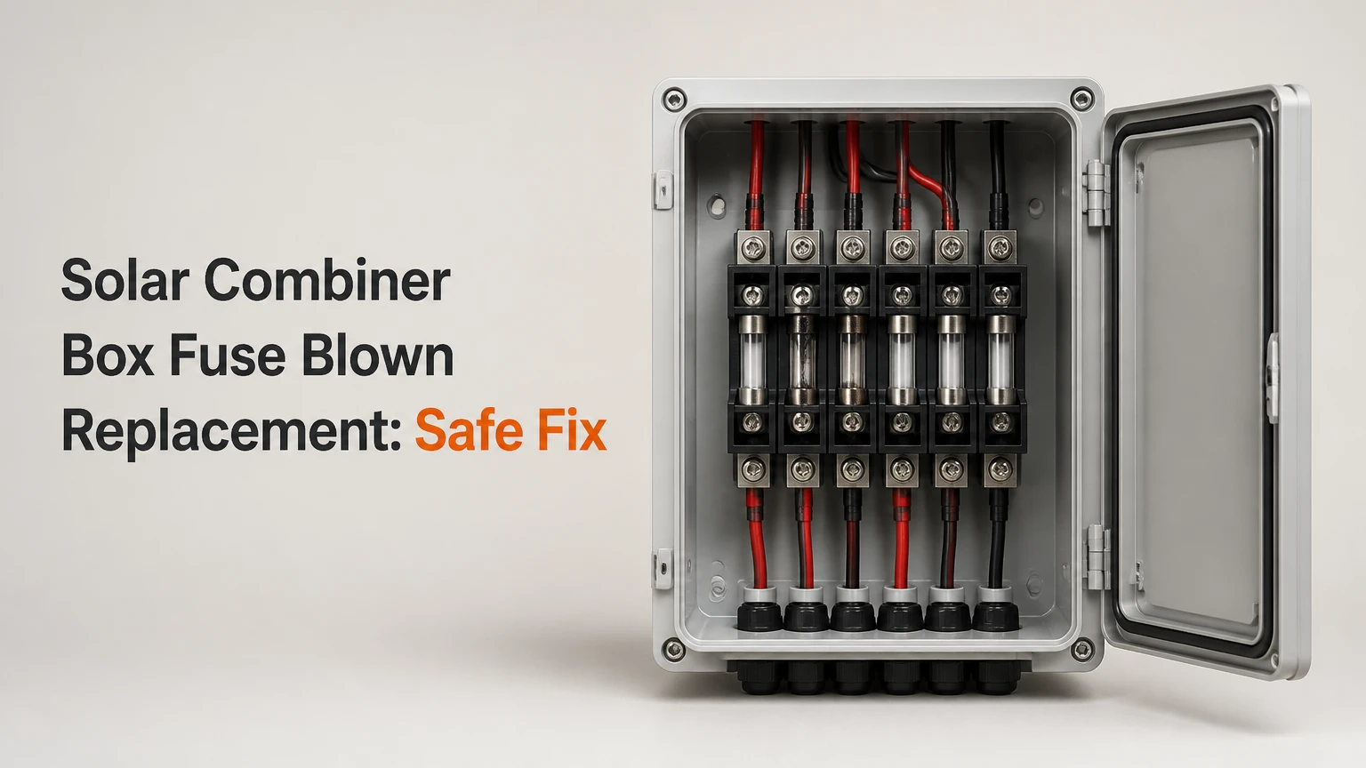
A solar combiner box fuse blown replacement requires a correctly rated DC photovoltaic fuse, verified isolation, and diagnosis of the original fault. Replace the fuse only with a compatible gPV fuse whose voltage, ampere rating, physical size, interrupt rating, and holder certification match the PV circuit and manufacturer instructions.
Key Facts
A PV fuse must carry a DC voltage rating at least equal to the array’s maximum cold-corrected open-circuit voltage.
The replacement ampere rating must not exceed the module’s maximum series fuse rating.
A combiner-box disconnect may isolate the output bus without making incoming PV string conductors safe to touch.
NEC 690.8 and the module data sheet determine conductor and overcurrent-device sizing; the fuse label alone is insufficient.
A melted holder, loose terminal, water ingress, or damaged connector requires more than a fuse change.
A new fuse that blows immediately usually indicates an unresolved short circuit, ground fault, reversed polarity, or damaged equipment.
What Does a Solar Combiner Box Fuse Protect?
A solar combiner box fuse protects an individual photovoltaic string from excessive reverse current supplied by parallel strings. The combiner connects several string positive and negative conductors to common output busbars, reducing multiple circuit pairs to a feeder pair leading toward an inverter or charge controller.
A string fuse is therefore different from an inverter input fuse or a large feeder fuse. The string device limits fault energy in module interconnections and conductors, while a feeder fuse protects the larger combined output circuit. Some small systems use an unfused combiner because the module’s maximum series fuse rating and the calculated available fault current do not require string overcurrent protection. The design documentation controls.
Photovoltaic fuses use the gPV classification defined in IEC 60269-6. In North American equipment, UL 248-19 covers photovoltaic fuses, while NEC Article 690 addresses PV overcurrent protection and disconnecting means. A fuse is not selected solely because it physically fits a fuse holder.
How does a PV fuse interrupt current?
A gPV fuse melts when fault current exceeds its time-current characteristic, then uses an arc-quenching medium and an enclosure designed for high-voltage direct current. Direct current lacks the alternating-current zero crossing that naturally helps extinguish an AC arc, so an AC-rated fuse can continue arcing after its element opens.
The fuse is sacrificial. A continuity test can confirm that the element is open, but continuity testing cannot prove that the string is safe to work on. Incoming modules can produce hazardous DC voltage whenever irradiance reaches them, even when the inverter is off.
Which Replacement Fuse Is Correct?
The correct replacement is a new gPV fuse that matches five linked specifications: DC voltage, ampere rating, physical dimensions, interrupting rating, and holder compatibility. The module data sheet, combiner label, electrical drawings, and fuse-holder markings should agree before installation.
Match the fuse to the lowest-rated component in the protected circuit. For example, a 15 A module maximum series fuse rating prevents installing a 20 A replacement merely because the conductor could carry more current. A fuse with the wrong body length may make poor contact, overheat, or fail to maintain the enclosure’s intended finger protection.
| Selection attribute | Required check | Typical PV example | Unsafe substitution |
|---|---|---|---|
| Classification | gPV, photovoltaic DC | IEC 60269-6 or UL 248-19 | AC glass fuse |
| Voltage | Fuse Udc ≥ cold-corrected array Voc | 1,000 Vdc or 1,500 Vdc | 600 Vac fuse |
| Current | Within calculated PV protection range | 15 A or 20 A | 30 A to stop nuisance blowing |
| Body size | Same holder format | 10×38 mm | 14×51 mm in a 10×38 holder |
| Interrupt rating | Greater than available DC fault current | 10 kA or manufacturer value | Unrated cartridge |
| Temperature | Holder and fuse ambient rating | 50°C to 70°C enclosure design | Indoor-only component |
What fuse size does a solar panel need?
The fuse size depends on short-circuit current, conductor ampacity, module maximum series fuse rating, temperature, and local electrical rules. A common NEC calculation begins with module Isc multiplied by 125% for continuous current and another 125% adjustment for expected irradiance conditions, producing 156% of Isc in many design calculations, but the final standard size and equipment limits still require a qualified designer’s review.
For a module with an Isc of 10.2 A, 10.2 × 1.25 × 1.25 equals 15.94 A. A 16 A fuse may be appropriate only if that standard size is available, the conductors support it, the module permits it, the holder is rated for it, and the design rules allow it. A 20 A fuse is not automatically acceptable.
| Example module and array data | Calculation or limit | Possible outcome |
|---|---|---|
| Isc = 8.5 A | 8.5 × 1.56 = 13.26 A | 15 A candidate, subject to module label |
| Isc = 10.2 A | 10.2 × 1.56 = 15.91 A | 16 A or approved next size |
| Isc = 12.0 A | 12.0 × 1.56 = 18.72 A | 20 A candidate if permitted |
| Maximum series fuse = 15 A | Absolute equipment limit | Do not install 20 A |
| Cold-corrected Voc = 1,040 V | Fuse and holder requirement | Use equipment rated above this voltage |
| Available fault current exceeds fuse rating | Interrupting requirement | Obtain an adequately rated device |
The 156% rule is a design starting point, not permission to increase a replacement fuse. The National Electrical Code changes by edition and jurisdiction, and local amendments can alter the applicable method. Use the adopted code, module instructions, and the combiner manufacturer’s engineering documentation.
Why does cold temperature affect fuse voltage?
Cold temperatures increase crystalline-silicon module open-circuit voltage, so the highest winter Voc, rather than the nameplate operating voltage, determines the required DC voltage rating. The array Voc calculation uses the module temperature coefficient and the local minimum design temperature, then multiplies the corrected module Voc by the number of modules in series.
A 1,000 Vdc fuse may be inadequate in an array whose cold-corrected string voltage approaches or exceeds 1,000 Vdc. A 1,500 Vdc fuse does not solve every issue, because the fuse holder, disconnect, cable insulation, surge protective device, and combiner enclosure must also carry the system voltage.
Which PV Fuse Formats Are Used?
Cylindrical midget fuses dominate small and residential combiner boxes, larger cylindrical bodies support higher string currents, and NH knife-blade fuses protect high-current commercial or utility feeders. The physical format must match the fuse base; electrical ratings alone do not make formats interchangeable.
| Fuse format | Typical voltage | Typical current | Common application |
|---|---|---|---|
| 10×38 mm cylinder | 600-1,000 Vdc | 2-32 A | Residential and small commercial strings |
| 14×51 mm cylinder | 1,000-1,500 Vdc | 20-50 A | Larger strings and sub-combiners |
| 22×58 mm cylinder | 1,000-1,500 Vdc | 32-100 A | High-current commercial feeders |
| NH00/NH0 | 1,000-1,500 Vdc | 100-250 A | Main combiner or feeder protection |
| NH1-NH3 | 1,000-1,500 Vdc | 250-630 A | Utility-scale busbars and feeders |
A fuse indicator light can speed identification, but it does not replace electrical testing. Some holders show a blown status through a mechanical flag or LED, while others provide no indication at all.
How Do You Replace a Blown Combiner Fuse?
A qualified PV electrician should replace a fuse in a high-voltage combiner box. The complete process commonly takes 15-30 minutes after arrival, but diagnosis can take one to several hours when insulation, connectors, or modules are involved. The success factor is proving a safe work condition, not simply installing a cartridge.
Before you start
| Requirement | Typical value or condition |
|---|---|
| Task difficulty | High-voltage DC electrical work |
| On-site replacement time | 15-30 minutes for a known fuse fault |
| Parts cost | $2-$6 for common 1,000 Vdc string fuses |
| Diagnostic service | $75-$150 typical truck-roll range |
| Required meter | CAT-rated meter, 1,000 Vdc or 1,500 Vdc as applicable |
| Other equipment | Insulated fuse puller, rated gloves, eye protection, torque tool |
| Required documents | Module data sheet, combiner drawing, fuse-holder instructions |
| Weather condition | Dry enclosure, no rain, no condensation, adequate light |
Do not open a wet enclosure, pull a fuse under load, or rely on the inverter display as proof of de-energization. OSHA 29 CFR 1910.333 requires qualified workers to de-energize, lock out or tag out, and verify circuits before work where applicable.
Step 1: Identify the affected circuit
Record the fuse position, string number, fuse marking, combiner model, and visible damage before touching the enclosure. Photograph labels and wiring so the original conductor placement can be restored.
Checkpoint: The damaged position and the intended replacement specification are documented.
Common mistake: Treating a burned fuse label as the complete fault diagnosis.
Step 2: Shut down connected equipment
Follow the exact shutdown sequence in the inverter and combiner manuals. Usually, the AC source is opened first, followed by the inverter’s DC input disconnect and the combiner’s output disconnect, but manufacturer procedures differ.
Checkpoint: Inverter status, AC breaker position, DC disconnect position, and lockout status are recorded.
Common mistake: Assuming the inverter’s DC switch disconnects voltage generated by every incoming PV string.
Step 3: Establish a safe work condition
Apply lockout and tagout where the installation allows it, restrict access, wear equipment rated for the measured voltage and arc-flash risk, and wait for inverter capacitors to discharge according to the manufacturer’s specified time.
A combiner output can read zero while an incoming string remains energized on the line side of its fuse. Qualified personnel must identify every energy source and test the exact conductors that will be handled.
Checkpoint: Each relevant source is isolated and the isolation status is controlled.
Common mistake: Measuring only the main busbars.
Step 4: Test the meter and measure voltage
Use a properly rated meter and leads. Prove the meter on a known source, test the relevant positive-to-negative, positive-to-ground, and negative-to-ground conductors, then prove the meter again.
Checkpoint: Measurements match the installation’s isolation plan and show the required safe voltage condition at the work points.
Common mistake: Using a non-CAT automotive multimeter or touching probes across unfamiliar terminals.
Step 5: Inspect the holder and surrounding wiring
Look for melted plastic, darkened metal, loose terminals, cracked insulation, water tracks, corrosion, insect debris, and heat-discolored conductor insulation. A blown element with a clean holder suggests a different fault from a holder that has visibly overheated.
Checkpoint: The holder, busbar, cable insulation, glands, and nearby surge protective device pass visual inspection.
Common mistake: Replacing a fuse inside a heat-damaged holder.
Step 6: Remove the fuse with an insulated tool
Open the finger-safe holder only after the required safe condition has been verified. Use the manufacturer-approved fuse puller, keep body parts clear of exposed conductive surfaces, and place the removed fuse in a controlled location.
Checkpoint: The fuse is removed without damage to the holder clips or fuse contacts.
Common mistake: Using pliers, a screwdriver, or bare fingers.
Step 7: Confirm the replacement specifications
Compare the new fuse against the old marking and design documents. Confirm gPV class, Udc, ampere rating, body dimensions, interrupt rating, manufacturer approval, and maximum series fuse restriction.
Checkpoint: Every electrical and mechanical attribute matches.
Common mistake: Matching only the ampere number printed on the cartridge.
Step 8: Install and torque connections
Install the new fuse in the correct orientation if the holder specifies one, close the holder fully, and torque any disturbed terminal to the manufacturer’s value. Typical PV terminal values can range from approximately 1.5-2.8 N·m, but the printed instruction always overrides a generic range.
Checkpoint: The fuse seats evenly, the holder closes, and the terminal torque is documented.
Common mistake: Guessing torque or retightening a spring clamp that the manufacturer says not to service.
Step 9: Test the PV string before energizing
Check string polarity, open-circuit voltage, and insulation resistance when the equipment and procedure call for it. A negative voltage reading can indicate reversed leads, but insulation faults may require a qualified megohmmeter test and module manufacturer limits.
Checkpoint: String voltage is plausible compared with neighboring strings, polarity is correct, and no unexplained ground fault remains.
Common mistake: Applying a megohmmeter voltage that exceeds the rating of connected electronics.
Step 10: Close, re-energize, and monitor
Replace barriers, check glands and door seals, close the enclosure, remove lockout controls under the approved procedure, and restore power in the manufacturer’s sequence. Compare string currents, inverter alarms, and temperatures with baseline values after irradiance stabilizes.
Checkpoint: The replacement fuse remains intact, string current is within expected variation, and no alarm or hot connection appears.
Common mistake: Declaring success immediately after the inverter starts.
Why Did the Solar Fuse Blow?
A blown PV fuse indicates that current exceeded the fuse’s time-current limit, but the initiating event may be a shorted module, connector, cable, ground fault, reverse polarity, water ingress, or an incorrectly sized component. The fuse protects the circuit; it does not identify which device failed.
| Symptom | Likely cause | Confirming check | Corrective action |
|---|---|---|---|
| Fuse opens immediately | Cable short or reversed polarity | Polarity and conductor inspection | Repair wiring before replacement |
| Fuse opens after rain | Moisture or insulation fault | Dry inspection and insulation test | Replace damaged connector or cable |
| Fuse opens on hot afternoons | Thermal derating or loose contact | Infrared scan under load | Correct torque, ventilation, or rating |
| Holder melts, fuse remains intact | High-resistance contact | Torque and thermal inspection | Replace holder and damaged conductors |
| One string has low current | Module, connector, or shading issue | Compare voltage and operating current | Test modules and connectors |
| All strings have zero output | Main fuse, disconnect, SPD, or inverter fault | Measure each stage safely | Diagnose feeder and protection devices |
A loose terminal can produce enough heat to destroy a holder without drawing enough current to melt the fuse element. This counterintuitive failure is why thermal inspection and torque records matter more than visual fuse inspection alone.
What should you do if the new fuse blows immediately?
Leave the replacement fuse open and stop re-energization. Repeatedly fitting new fuses can increase arc, fire, and equipment damage risk while masking the original short circuit.
Test the string for reversed polarity, damaged insulation, crushed cable, failed connectors, and module junction-box faults. Check whether a surge protective device has operated, but do not assume the SPD caused the fuse failure. A qualified technician should isolate sections of the string and test them against the manufacturer’s limits.
Why Are AC Fuses and Automotive Fuses Unsafe?
AC fuses and automotive fuses are unsafe substitutes because their voltage, arc-interruption construction, environmental rating, and time-current behavior may not support PV direct current. An AC fuse rated for 600 Vac is not equivalent to a 600 Vdc photovoltaic fuse.
Automotive blade fuses also lack the required PV DC voltage and interrupting performance for many combiner circuits. A fuse that physically fits can still sustain an arc, rupture violently, or fail to protect the conductor.
The same warning applies to a higher-ampere gPV fuse. Oversizing from 15 A to 30 A may allow fault current to heat module leads and connectors beyond their insulation rating before the protection operates.
Fuse or DC Circuit Breaker: Which Is Better?
A gPV fuse generally offers lower purchase cost and high-voltage fault interruption, while a listed PV DC circuit breaker provides reset capability and easier status indication. Neither option is universally superior; the correct choice depends on voltage, available fault current, maintenance access, space, and the equipment listing.
| Decision factor | gPV fuse | PV DC circuit breaker | Practical consequence |
|---|---|---|---|
| Common string price | $2-$6 each | $25-$80 typical | Fuses cost less initially |
| Reset capability | No, replace element | Yes, if fault is cleared | Breakers reduce spare inventory |
| 1,000-1,500 Vdc availability | Common in specialist ranges | More expensive and larger | Fuses suit high-voltage arrays |
| Status indication | Optional LED or flag | Handle and trip indication | Breakers simplify field checks |
| Fault interruption | Manufacturer-specific, often 10 kA or higher | Manufacturer-specific | Compare tested DC ratings |
| Maintenance risk | Pulling under load is hazardous | Switching under load may be listed | Follow device instructions |
| Repeated faults | Requires replacement each time | Can repeatedly trip | Resetting without diagnosis remains unsafe |
A breaker is not automatically safer. A breaker must be listed for the PV voltage, polarity, fault current, enclosure, and operating duty, and its terminal temperature rating must suit the installation.
What Does Replacement Cost?
A common 10×38 mm gPV fuse costs approximately $2-$6, while a larger NH feeder fuse commonly costs $30-$70. Professional service typically adds $75-$150 for a diagnostic visit, with total cost rising when a holder, connector, cable, SPD, or module requires replacement.
| Service item | Typical price range | Typical time | Main cost variable |
|---|---|---|---|
| 10×38 mm gPV fuse | $2-$6 | 5-10 minutes | Brand and voltage rating |
| Larger cylindrical fuse | $8-$25 | 10-20 minutes | Body size and interrupt rating |
| NH feeder fuse | $30-$70 | 15-30 minutes | Current and voltage class |
| Diagnostic truck roll | $75-$150 | 30-90 minutes | Region and access |
| Fuse-holder replacement | $15-$100 | 30-90 minutes | Format and busbar design |
| Connector or cable repair | $20-$250+ | 30-180 minutes | Fault location and roof access |
These are typical North American service ranges, not published universal prices. Utility-scale equipment, rooftop access, emergency callouts, and arc-flash procedures can increase labor substantially.
Which Field Mistakes Cause Repeat Failures?
The most expensive mistake is treating a blown fuse as a consumable nuisance rather than a fault indicator. Other repeat failures result from incorrect ratings, poor contact pressure, unsafe testing, and environmental damage.
- Installing the next larger fuse: The replacement must remain below the module’s maximum series fuse rating and within the calculated protection design.
- Ignoring the holder: A heat-damaged clip adds contact resistance and can destroy a new fuse.
- Pulling under load: Disconnecting a cartridge while current flows can create a sustained DC arc.
- Skipping polarity checks: Reversed string conductors can cause immediate operation or abnormal current sharing.
- Trusting a continuity test alone: An open fuse proves failure, not safe isolation or the cause.
- Leaving moisture unresolved: Water inside connectors, glands, or fuse compartments can create intermittent insulation faults.
- Mixing undocumented parts: Fuse and holder listings, dimensions, voltage, and terminal limits must remain compatible.
Should You Replace the Fuse Yourself?
A homeowner should limit DIY work to documenting labels, checking the manufacturer’s manual, and arranging service unless the person is trained and authorized for the system’s DC voltage and arc-flash hazards. Small physical size does not make a 1,000 Vdc combiner safe.
A trained commercial technician may replace a documented string fuse after approved isolation and testing. Utility-scale NH fuses, energized testing, insulation-resistance testing, and damaged busbars require site-specific procedures, calibrated equipment, and qualified personnel.
The system is not suitable for casual troubleshooting if the enclosure is wet, a fuse holder is melted, conductors are charred, the array exceeds the worker’s test-equipment rating, or the replacement opens again.
FAQ
Can sunlight be turned off for solar fuse work?
No. Standard PV modules generate voltage whenever light reaches them, so shutting down the inverter does not turn off the array. Safe work requires isolating all accessible energy sources, controlling stored energy, and verifying the actual conductors before contact.
Does every solar combiner box contain a fuse?
No. Some combiner designs are unfused when the calculated reverse-current risk, module ratings, conductor ampacity, and system configuration permit that arrangement. Never add or remove protection based on appearance; use the equipment drawing and adopted electrical code.
How can I tell whether a PV fuse is blown?
A blown fuse may show a mechanical indicator, LED, darkened element, or open circuit on a properly performed continuity test. Visual and continuity checks identify a failed fuse, but they do not prove that the circuit is de-energized or explain why the fuse opened.
Can shading blow a solar string fuse?
Ordinary localized shading usually reduces current rather than blowing a correctly sized fuse. A fuse may open when shading combines with a module, bypass-diode, connector, or wiring fault that causes abnormal current or reverse current, so shading alone should not be accepted as the diagnosis.
Should both positive and negative string fuses be replaced?
Replace only the failed fuse unless the manufacturer, design, or inspection requires paired replacement. Some combiner boxes fuse one polarity, while others fuse both, and replacing an intact fuse can introduce a mismatched component or disturb a sound connection.
How long should a replacement fuse last?
A correctly selected and installed gPV fuse can remain in service for years, but service life depends on temperature cycling, connector quality, fault exposure, and holder condition. A second failure soon after replacement indicates an unresolved system problem rather than normal fuse wear.
The Bottom Line
Solar combiner box fuse blown replacement is safe only when the replacement is a compatible gPV DC fuse and the original fault has been investigated. Confirm cold-corrected voltage, Isc-based sizing, maximum series fuse rating, interrupt capacity, body format, holder condition, polarity, and torque before restoring power. If the fuse blows again, stop replacing fuses and diagnose the string, wiring, connectors, insulation, SPD, and feeder protection.