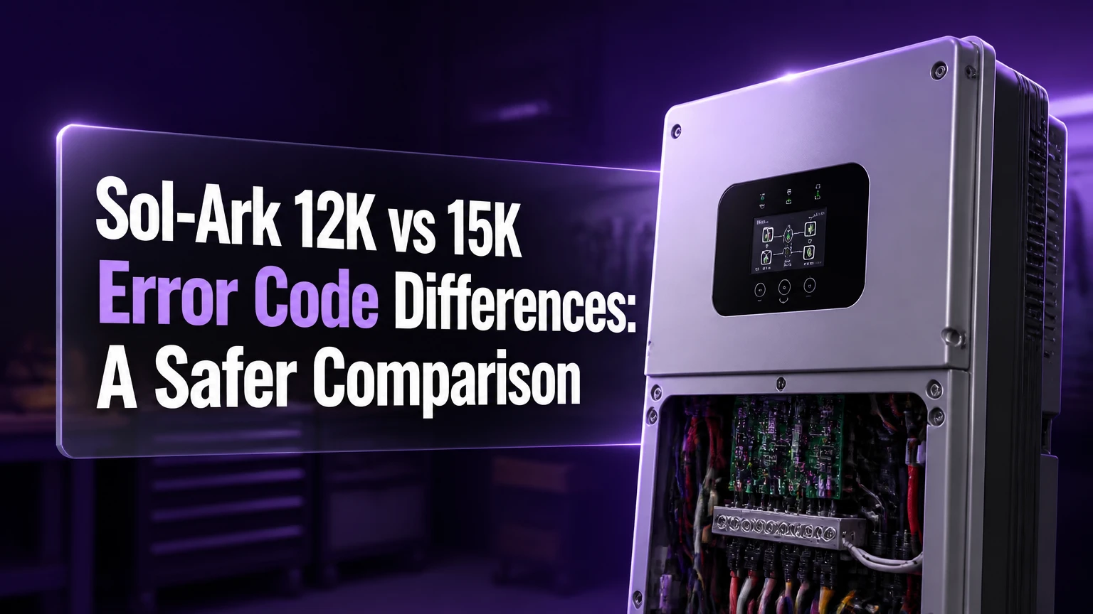
Sol-Ark 12K vs 15K error code differences are usually caused by hardware limits, firmware revisions, system wiring, and operating mode rather than entirely separate code libraries. The two inverters share many alarm labels, but identical labels do not guarantee identical thresholds or root causes, so the model number, firmware version, event history, and electrical conditions must be checked together.
Key facts at a glance
Sol-Ark 12K and 15K fault labels overlap substantially, but their protection limits are not interchangeable.
F26 should be treated as a bus or internal balance fault until the applicable manual confirms a load-balance diagnosis.
F15 and F18 generally indicate AC-side overcurrent protection, while F20 indicates a DC-side overcurrent event.
Code 63 requires inspection of PV connectors, conductors, polarity, moisture, and insulation before reset.
F58 usually points to a battery-management-system communication problem, not automatically a failed battery.
The first chronological alarm is more useful than later cascade alarms such as a parallel-stop or system-shutdown message.
What Are the Sol-Ark 12K vs 15K Error Code Differences?
The main difference is not a simple list in which every fault belongs exclusively to the 12K or 15K. Sol-Ark assigns many diagnostic labels across product families, while the inverter’s sensors, power semiconductors, contactors, bus structure, firmware, and installation determine when protection activates. A 12K and a 15K can therefore display the same code after different electrical events.
Sol-Ark documentation should control interpretation. The 12K product family includes different revisions and configurations, and a 15K can also receive firmware updates that alter descriptions, warnings, or recovery behavior. A code copied from a forum post may be useful as a clue, but it is not a substitute for the manual matching the exact inverter serial number and revision.
| Comparison point | Sol-Ark 12K, commonly published value | Sol-Ark 15K, commonly published value | Diagnostic consequence |
|---|---|---|---|
| Rated AC output | 9 kW continuous | 15 kW continuous | The 12K reaches sustained output limits sooner |
| Maximum PV input | Approximately 11-13 kW, revision dependent | Approximately 19.2-19.5 kW, revision dependent | String design changes DC alarm exposure |
| MPPT count | Commonly 2 | Commonly 3 | Affected string location matters |
| Battery discharge rating | Approximately 8-9 kW, configuration dependent | Approximately 12 kW | Battery current can trigger protection before inverter output rating |
| Service pass-through | Often configured around 63 A maximum | Commonly configured for 200 A service pass-through | Whole-home topology differs |
| Battery connection arrangement | Model and revision dependent | Model and revision dependent, often dual inputs | Port count alone does not prove communication redundancy |
The figures above are commonly published product values, not universal diagnostic thresholds. Installer settings, breaker ratings, ambient temperature, battery limits, firmware, and local electrical design can produce different results.
Why Can the Same Code Behave Differently?
The same Sol-Ark code behaves differently when the two inverters measure different current, voltage, temperature, or bus conditions. A 15K has greater AC conversion capacity and a different power path, while a 12K may reach its current, thermal, or bus limits with the same household load.
The distinction matters most during off-grid operation. Grid power can absorb or supply transients that the inverter must handle alone when islanded. A compressor, well pump, heat pump, or transformer may therefore produce a fault during battery operation without producing one on the grid.
The National Fire Protection Association states in NFPA 70, Article 110.3(B), “Listed or labeled equipment shall be installed and used in accordance with any instructions included in the listing or labeling.” That requirement makes the exact Sol-Ark manual and installation instructions more authoritative than generalized code charts.
Which specifications matter during diagnosis?
Rated output is only one variable. Battery discharge current, surge duration, MPPT current, conductor length, breaker size, neutral configuration, and temperature can all determine whether the inverter continues operating.
| Operating condition | 12K practical implication | 15K practical implication | Useful diagnostic question |
|---|---|---|---|
| 120 V motor starts | More likely to approach its available phase or surge margin | More available conversion headroom | Did the event occur at motor startup? |
| Large 240 V HVAC load | Can approach the 9 kW AC rating quickly | Has more sustained output capacity | What was the measured load at fault time? |
| Battery-limited output | Battery may restrict output below inverter rating | A 15K still cannot exceed battery or BMS limits | Did the battery BMS report overcurrent? |
| High PV voltage | Exceeding MPPT voltage can damage equipment | Three trackers do not permit excessive string voltage | What are cold-weather string Voc values? |
| Whole-home pass-through | Service design may require a critical-load panel | 200 A pass-through may simplify service integration | Is the fault inverter output or bypass current? |
Which Fault Codes Differ Most in Practice?
F15, F18, F20, F26, F58, and Code 63 attract the most comparison questions, but their meanings must be tied to the specific manual. The 15K does not automatically prevent these events, and the 12K does not automatically produce them under ordinary household use.
F15 and F18: AC overcurrent protection
F15 and F18 are generally associated with AC-side overcurrent protection, but the exact label and trigger can differ by firmware. A locked-rotor compressor, short circuit, incorrectly sized conductor, simultaneous motor startup, or excessive sustained output can all be relevant.
The 12K’s lower continuous AC rating gives it less headroom in a high-demand off-grid system. The 15K may ride through the same legitimate starting event, but a 15K still trips when the load exceeds its programmed or hardware limits. A higher rating does not make a short circuit safe.
Diagnostic sequence:
- Record whether the inverter was on-grid, off-grid, or transitioning.
- Identify the first load that started before the event.
- Check AC output current and battery discharge current.
- Inspect breakers, lugs, neutral conductors, and heat damage.
- Test large motors individually rather than restarting every circuit together.
Do not use a claimed figure such as “37.5 A per leg” as a universal 12K threshold. Actual limits depend on the product revision, voltage, phase, firmware, and whether the value refers to continuous output, bypass, or a protection threshold.
F26: Bus unbalance or internal balance fault
F26 is best approached as a bus-unbalance or internal balance protection event, not as proof that one household leg simply has too many 120 V appliances. Some installers associate the code with phase loading because uneven loads can expose limited system headroom, but the code’s exact meaning is model and firmware dependent.
The difference is important. Moving a load from L1 to L2 may reduce an operating imbalance, yet it cannot repair a damaged sensor, DC bus problem, loose connection, or failed power board. A recurring F26 with minimal load requires service diagnosis rather than repeated panel rearrangement.
| F26 investigation | Evidence to collect | Likely next action | Stop condition |
|---|---|---|---|
| Off-grid motor event | Load name, startup time, AC current | Test motor separately | Repeated trip with motor disconnected |
| Uneven 120 V loading | L1 and L2 current under the same conditions | Have electrician rebalance circuits | Neutral heating or discoloration |
| Internal bus concern | Fault recurrence at low load | Contact Sol-Ark support | F26 returns after verified isolation |
| Parallel system event | Unit ID and synchronization status | Inspect communication and phase settings | Multiple units fault together |
| Thermal event | Heatsink temperature and ventilation | Correct clearance and airflow | Hot smell, melted insulation, or smoke |
F20: DC overcurrent protection
F20 generally identifies a DC-side overcurrent condition. The cause may involve PV input current, a battery-side event, a shorted component, incorrect polarity, or a current sensor issue, depending on the code dictionary for the inverter revision.
A 15K’s additional MPPT does not make poor string design harmless. Every string must remain within the tracker’s voltage and current limits, including cold-weather open-circuit voltage and parallel-string current. The relevant calculation uses the module manufacturer’s temperature coefficient and the site’s minimum design temperature, not only the panel label at standard test conditions.
Code 63: arc-fault detection
Code 63 indicates an arc-fault detection event in systems where that code is used. It is a safety event, not a routine nuisance notification. Repeatedly clearing Code 63 without inspection can leave a damaged connector, loose terminal, rubbed conductor, or wet junction energized.
A qualified person should isolate the PV array according to the Sol-Ark installation procedure, then inspect MC4-compatible connectors, crimp quality, conductor insulation, roof penetrations, combiner equipment, polarity, and signs of heat. An insulation-resistance or circuit test may be necessary. Never open energized PV connectors under load.
How Do Battery and Communication Faults Differ?
F58 is commonly associated with BMS communication failure, but the inverter’s response depends on battery protocol, cable pinout, termination, firmware, and the selected battery brand profile. A communication fault does not by itself prove that the lithium battery cells or inverter board have failed.
CAN and RS485 are not interchangeable simply because both use modular connectors. The RJ45 plug shape does not establish pin compatibility. A battery manufacturer’s Sol-Ark cable diagram, protocol selection, baud settings, termination requirements, and firmware support must all agree.
| F58 check | Correct evidence | Common failure | Recovery path |
|---|---|---|---|
| Battery protocol | Named supported profile | Generic lithium profile selected incorrectly | Apply manufacturer-approved profile |
| Communication cable | Pinout and cable part number | Ethernet patch cable used as a battery cable | Replace with approved cable |
| Battery status | BMS online state and alarms | Battery breaker on but BMS asleep | Wake battery and verify BMS |
| Addressing | DIP switch or software address | Duplicate battery addresses | Correct addressing and restart |
| Charge limits | Voltage, current, and temperature limits | Inverter exceeds BMS permission | Correct limits before reconnecting |
Some systems can operate in open-loop voltage mode, but that removes closed-loop current and state-of-charge coordination. Do not disable a BMS stop function merely to suppress F58 unless Sol-Ark and the battery manufacturer approve the configuration.
What About F55, F16, F8, F41, F47, and F59?
Secondary codes need context because some appear after the original fault. F41, for example, may indicate a parallel or system stop condition after another inverter or communication event. Clearing F41 without finding the first alarm often produces a temporary restart followed by another shutdown.
| Code or label | Area to investigate | What it does not prove | First check |
|---|---|---|---|
| F55 | AC voltage or AC input condition | A utility surge is the only cause | Measure L1-L2, L1-neutral, and L2-neutral |
| F16 | Ground-fault or leakage-related protection | Neutral-ground bonding is always wrong | Verify bonding and grounding against the approved diagram |
| F8 | Grounding, relay, or protection condition, revision dependent | A single appliance caused the event | Inspect wiring and manual definition |
| F41 | Parallel or system stop condition | F41 was the original trigger | Read earlier alarms and unit IDs |
| F47 | Grid or AC operating condition, revision dependent | Battery replacement will fix it | Check grid quality and mode settings |
| F59 | Grid, synchronization, or protection condition, revision dependent | Rural utility instability is confirmed | Capture voltage and frequency data |
The AI Overview’s claim that double-bonded neutral and ground always produce F16 or F8 is too definite. Improper bonding can create objectionable current or protection problems, but the displayed code depends on the wiring topology, sensing method, and firmware.
How Should You Troubleshoot a Sol-Ark Fault Safely?
A Sol-Ark fault should be diagnosed from the first chronological event, with the affected energy source isolated before any reset. A safe investigation usually takes 15-30 minutes for a configuration issue, while a suspected wiring or hardware problem requires a qualified electrician and possibly Sol-Ark support.
Step 1: Record the operating state
Write down the code, timestamp, battery state of charge, grid status, PV production, load watts, and equipment that started immediately before the fault. Photograph the display and save the Sol-Ark monitoring history before clearing alarms.
Step 2: Isolate only under the approved procedure
Turn off loads, grid input, PV disconnects, and battery protection devices in the sequence specified by the exact Sol-Ark manual. Do not remove covers, loosen terminals, or probe internal DC buses. PV circuits can remain hazardous even when the AC panel is off.
Step 3: Read the alarm history
Find the earliest code in the event sequence. Treat later parallel-stop, communication-loss, or shutdown messages as possible consequences until the chronology proves otherwise.
Step 4: Match the code to the exact model
Confirm the full model name, firmware version, serial number, and revision date. Compare the code with the official Sol-Ark manual, not a 12K chart applied to a 15K or a three-year-old forum post.
Step 5: Test one variable at a time
For an AC event, reconnect grid and loads separately. For a PV event, keep the array isolated until wiring is inspected. For F58, verify the battery protocol and cable before changing charge parameters.
Step 6: Recommission in the documented order
A common manufacturer procedure uses battery first, followed by PV, grid, and loads, but the exact order must come from the applicable manual. A five-minute waiting period may be recommended for a complete shutdown, yet capacitor discharge should never be assumed safe merely because a timer expired.
Stop immediately for smoke, melted insulation, repeated arc faults, tripped upstream protection, burning odor, exposed conductors, battery swelling, or a fault that returns with all external sources isolated.
Does the 15K Have Fewer Error Codes?
The Sol-Ark 15K does not necessarily have fewer error codes. The 15K may produce fewer nuisance overcurrent events in a larger home because its continuous output and service pass-through capacity are higher, but it still has PV, battery, grid, thermal, ground-fault, communication, and internal hardware protections.
The 12K can be a dependable choice when the critical-load panel remains below its continuous output and surge capability. It is a poor fit for an unmanaged whole-home load profile containing multiple large motors, electric resistance heating, and frequent simultaneous starts.
Which model suits each installation?
| User situation | Better fit | Reason | Limitation |
|---|---|---|---|
| Managed cabin loads below 9 kW | Sol-Ark 12K | Lower output class suits controlled demand | Motor starts need testing |
| Whole-home 200 A service integration | Sol-Ark 15K | Higher pass-through capacity may simplify topology | Higher equipment and installation cost |
| Several HVAC compressors | Sol-Ark 15K | More AC and surge headroom | Battery must supply required current |
| Small critical-load subpanel | Sol-Ark 12K | Circuit selection limits overload risk | Requires disciplined load management |
| Battery communication experiment | Neither without approval | Protocol compatibility matters more than model size | Unsupported firmware can create F58 events |
The 15K is not automatically the better off-grid inverter. A poorly sized battery, undersized conductors, incorrect phase configuration, or excessive PV string voltage can fault a 15K just as effectively as a 12K.
How Much Do Diagnosis and Repair Usually Cost?
Remote configuration diagnosis is often free when covered by manufacturer support or an installer agreement. Typical electrician troubleshooting costs range from $150-$400 for a site visit, while wiring repairs, replacement connectors, surge protection, or battery communication work can raise the total to $400-$1,200.
Internal board replacement is highly variable. A typical out-of-warranty repair may reach $600-$1,500 for parts and labor, excluding shipping, travel, and permit work, but these are market ranges rather than Sol-Ark price guarantees. Warranty eligibility depends on installation, registration, environmental conditions, and the failure assessment.
| Service action | Typical timeframe | Typical cost range | Usually requires |
|---|---|---|---|
| Alarm-log review and settings correction | 15-30 minutes | $0-$150 | Installer or remote support |
| Battery cable and protocol correction | 30-90 minutes | $100-$350 | Battery documentation |
| PV connector or conductor repair | 1-4 hours | $200-$900 | Qualified solar electrician |
| Grid and grounding investigation | 1-3 hours | $150-$600 | Licensed electrician |
| Internal inverter repair | 3-7 business days or longer | $600-$1,500 typical | Sol-Ark or authorized service |
What Mistakes Create Repeat Faults?
The most expensive troubleshooting mistake is resetting a code before preserving the event history. A reset removes context, while the original condition may still exist in the array, battery, panel, or utility supply.
Three practitioner rules prevent many repeat failures:
- Treat Code 63 as a physical inspection event. Do not clear it repeatedly.
- Separate inverter limits from battery limits. A 15K cannot deliver 12 kW if the battery BMS permits only 6 kW.
- Test transitions, not only steady loads. Many faults occur when grid transfer, motor startup, battery charging, and PV ramping overlap.
Batteryless operation also deserves caution. Some grid-connected systems can operate without batteries in defined modes, but backup and off-grid stability requirements differ. A rural grid with rapid voltage or frequency variation can expose control limitations, and the correct response is configuration review rather than assuming a battery is universally mandatory.
Which Sol-Ark Should You Choose?
Choose the Sol-Ark 15K for a high-demand whole-home system with large motors, substantial battery capacity, and a service design that benefits from higher pass-through capability. Choose the Sol-Ark 12K for a controlled critical-load or cabin installation where the installer can manage circuit selection, phase loading, PV design, and battery limits.
The 12K is not good for an unmanaged panel containing electric water heating, multiple HVAC systems, welders, and pump motors that can start together. The 15K is not good for an installation with a small battery bank, unsupported BMS communications, or PV strings that exceed cold-weather voltage limits.
Best fit for a budget-conscious cabin
Select the 12K when continuous demand remains below its rated output and high-starting-current equipment is tested individually. A critical-load panel and load-shedding strategy provide more protection than simply moving circuits between phases after faults appear.
Best fit for whole-home backup
Select the 15K when the service entrance, battery bank, transfer equipment, and local code design support its larger pass-through and output class. The installer must still verify neutral handling, grounding, available fault current, and utility interconnection requirements.
Best fit for technically managed systems
Either model can work when monitoring is active and the owner records alarm chronology, firmware, battery status, and operating mode. Solar-Assistant or Modbus monitoring can add useful visibility, but third-party monitoring does not replace manufacturer service data or electrical testing.
FAQ
Are Sol-Ark 12K and 15K fault-code numbers interchangeable?
No. Shared labels may have similar meanings, but definitions and thresholds can vary by model revision and firmware. Confirm the full model, firmware version, and manual before applying a diagnostic procedure. A code table from a 12K should not be treated as authoritative for a 15K.
Can an F58 code damage a lithium battery?
F58 normally indicates loss of inverter-to-BMS communication, not direct cell damage. The risk arises when communication loss causes incorrect charge or discharge control, especially if the system is forced into open-loop operation. Keep the battery isolated until protocol, cable pinout, limits, and BMS status are verified.
Why does a fault happen only when the system is off-grid?
The grid can supply short-duration starting current and stabilize voltage while the inverter is connected. During off-grid operation, the inverter and battery must supply the transient alone, so motor inrush, phase imbalance, battery current limits, and weak connections become more visible.
Should I rebalance circuits to fix F26?
Circuit balancing may reduce stress in some installations, but F26 is not proof of ordinary household phase imbalance. First verify the code definition for the exact inverter and inspect event conditions. If F26 returns under low load or with external circuits isolated, seek qualified service rather than repeatedly moving breakers.
Can I clear Code 63 from the touchscreen?
The touchscreen may provide an arc-fault reset function, but reset only after the PV array and wiring have been inspected under a safe isolation procedure. A recurring Code 63 can indicate arcing, damaged connectors, moisture, or insulation failure, all of which create fire risk.
When should Sol-Ark support be contacted?
Contact Sol-Ark or an authorized installer when a fault returns after verified external isolation, when an internal bus or sensor fault is suspected, when parallel units fail together, or when the display shows heat, smoke, damaged wiring, or repeated arc-fault events. Provide photographs, alarm chronology, firmware, battery model, and operating mode.
Conclusion
The practical Sol-Ark 12k vs 15k error code differences come from output capacity, pass-through design, battery capability, PV architecture, firmware, and installation conditions, not from a simple 12K-versus-15K code list. Use the exact manual, preserve the first alarm, isolate hazards before resetting, and choose the 15K for higher unmanaged demand or the 12K for a deliberately controlled critical-load system.