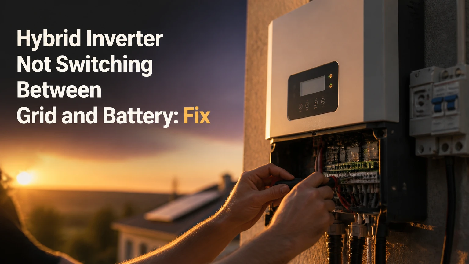
A hybrid inverter not switching between grid and battery usually has a blocked operating condition, such as an invalid grid profile, low battery reserve, BMS communication loss, overload, or transfer-device fault. Identify whether the failure occurs during grid loss, grid return, or both, then check status data before testing breakers or opening equipment.
Key Facts
A hybrid inverter may refuse battery discharge when reserve SoC, temperature, voltage, or BMS limits are active.
Grid transfer thresholds are model-specific; 180 V and 10-20 milliseconds are not universal values.
A backup inverter can remain powered while its backup loads are dead because the backup breaker, output relay, or load circuit has failed.
Lithium batteries generally require an active BMS communication link before a compatible inverter will discharge them.
Switching the utility breaker is a functional test, not proof of a failed internal relay, and only qualified personnel should perform live electrical work.
A whole-home system and a critical-loads system can behave differently even when both use hybrid inverters.
Why Is My Hybrid Inverter Not Switching Between Grid and Battery?
The most likely cause is a protection or permission condition, not an immediately failed inverter. Hybrid inverters block transfer when they detect unsafe grid voltage or frequency, insufficient battery charge, a BMS warning, excessive load, incompatible settings, or an open backup circuit.
Start by recording the exact symptom. A system that stays on but shows “grid available” has a different fault path from a system that shuts down completely. A system that transfers to battery and then trips usually has a load, battery-current, or thermal problem.
The National Electrical Code, NFPA 70, and utility interconnection rules require anti-islanding behavior. A grid-connected inverter must disconnect from the utility during abnormal conditions rather than energize external lines. The inverter therefore cannot be judged faulty merely because it refuses to operate while its grid measurements remain outside the permitted profile.
Separate the Failure Direction
| Observed symptom | Likely subsystem | First safe check | Typical next action |
|---|---|---|---|
| Grid fails, home loses backup power | Backup output, battery permission, transfer relay | App status and fault log | Check reserve, BMS, backup breaker |
| Grid returns, battery keeps supplying loads | Grid sensing, return threshold, AC input | Grid voltage and frequency status | Check grid profile and AC isolator |
| Inverter shuts off completely | DC battery path, internal control power, severe fault | Display, LEDs, battery breaker status | Installer diagnosis |
| Backup starts, then trips | Load surge, overload, battery current limit | Remove large loads and review event | Load separation or settings review |
| Inverter repeatedly changes modes | Weak grid, narrow hysteresis, generator interaction | Event timestamps and grid readings | Utility or installer investigation |
| Battery shows online but never discharges | SoC reserve, schedule, BMS permission | Charge and discharge settings | Correct schedule or communication |
How Does Automatic Grid-to-Battery Transfer Work?
A hybrid inverter measures utility voltage and frequency, opens a grid-isolation device when the grid is unacceptable, establishes a permitted island, and supplies designated loads from the battery. The process can be internal to the inverter or controlled by an external gateway, backup switch, or automatic transfer switch.
The power path is normally arranged as follows:
| Power source or load | Electrical form | Controlled by | Common location |
|---|---|---|---|
| Solar array | Direct current, often 100-600 VDC | MPPT trackers | Rooftop and DC isolator |
| Battery bank | 12, 24, 48, or high-voltage DC | BMS and battery converter | Battery cabinet |
| Utility supply | 120/240 VAC or 230/400 VAC | AC sensing and grid relay | Main distribution board |
| Inverter output | Synchronized or islanded AC | Inverter bridge and transfer device | Backup-loads panel |
| Household equipment | AC loads with motor surges | Breakers and load circuits | Main or essential-loads panel |
During normal operation, the inverter synchronizes its AC waveform with the utility. During a grid outage, the inverter must isolate the protected loads from utility conductors before creating local AC power. The transfer time depends on the model, operating mode, load, and whether an external contactor moves.
Is 10-20 Milliseconds a Universal Switching Time?
No. A 10-20 millisecond transfer is typical for some standby hybrid systems, but it is not a universal specification. Some equipment briefly interrupts power, some provides UPS-style continuity for selected outlets, and some external transfer switches take longer than internal electronic transfer paths.
Check the installation manual for “backup transfer time,” “UPS mode,” or “seamless transfer.” IEEE 1547-2018 governs interconnection behavior in the United States, while EN 50549 applies to many European grid-connected installations; neither standard guarantees one universal household transfer time. A desktop computer may tolerate the interruption, while a sensitive medical device may require a separately certified UPS.
What Should You Check Before Troubleshooting?
Record the inverter model, battery model, firmware versions, fault codes, current operating mode, displayed SoC, grid readings, and affected circuits before changing settings. This record prevents a common diagnostic error: clearing an alarm without identifying the condition that caused the transfer block.
Before You Start
| Item | Typical requirement | Why it matters |
|---|---|---|
| Diagnostic time | 20-45 minutes | Status review and non-invasive checks |
| Tools | Inverter app, manual, flashlight, phone camera | Documents settings and alarms |
| Electrical skill | Homeowner checks only on accessible controls | Covers no live panel work |
| Battery condition | Above reserve threshold, no critical alarm | Allows discharge permission |
| Data to record | Model, serial, codes, SoC, temperatures | Enables accurate support escalation |
| Safety boundary | No covers, terminals, or bypasses opened | DC arcs and mains voltage can injure |
Do not remove inverter covers, defeat an interlock, bridge a relay, or disconnect battery communication cables while energized. Battery packs can deliver very high fault current, and anti-islanding protections must remain active.
Step 1: Read the Operating State and Event Log
Open the inverter display or monitoring portal and identify whether the unit reports grid-tied, standby, backup, fault, battery charging, or battery discharging mode. Save the exact warning text, because “battery unavailable,” “AC input out of range,” and “backup overload” indicate different repairs.
Check whether the alarm is active or historical. A historical grid event may explain a previous outage without explaining the current failure. Also verify that the monitoring portal is current; a communication outage can make a healthy inverter appear frozen.
Success checkpoint: The display shows current grid status, battery status, and the last transfer event with a timestamp.
Common mistake: Treating an app connection error as a power-conversion failure.
Step 2: Confirm Battery SoC, Temperature, and Permission
Verify the battery’s displayed SoC against the inverter’s minimum backup reserve, minimum discharge SoC, and scheduled operating mode. A battery showing 25% may be unavailable if the reserve is set to 30%, while cold or overheated lithium cells may block discharge even at 80%.
The reserve value is not the same as battery health. A 10 kWh battery with a 20% reserve may expose roughly 8 kWh before reserve protection, but inverter efficiency, power limits, and manufacturer limits reduce usable AC energy.
| Battery condition | Typical display or state | Transfer consequence | Correct response |
|---|---|---|---|
| Reserve reached | 10-30% SoC setting | Discharge blocked | Charge above reserve |
| Low cell voltage | BMS protection event | Battery output disabled | Follow battery reset procedure |
| Low temperature | Often below 0°C for charging limits | Charge blocked; discharge may vary | Warm battery within manufacturer limits |
| High temperature | Cabinet or cell alarm | Current reduced or output stopped | Improve ventilation and wait |
| Schedule restriction | Timed reserve or grid-only mode | Battery remains idle | Review time-of-use settings |
| Battery breaker open | No DC power path | Inverter cannot discharge | Qualified inspection if inaccessible |
Do not repeatedly force a deeply discharged battery to start. Lithium batteries can require a controlled recovery process, and a BMS may need authorized wake-up instructions.
Step 3: Verify BMS Communication and Compatibility
A lithium hybrid system normally needs closed-loop communication between the battery BMS and inverter. CAN bus or RS485 carries SoC, voltage, temperature, charge-current, discharge-current, and protection states; if those values disappear or become implausible, the inverter commonly defaults to no-discharge operation.
Inspect only accessible, de-energized connectors and compare the communication protocol with the approved compatibility list. RJ45-shaped connectors are not automatically Ethernet-compatible, and two devices can use the same physical connector with different pinouts.
| Compatibility item | Example value | Failure symptom | Verification source |
|---|---|---|---|
| Battery nominal voltage | 48 V or 400 V class | DC undervoltage or no start | Inverter manual |
| Communication type | CAN or RS485 | BMS timeout | Battery manual |
| Protocol profile | Pylontech, BYD, proprietary | Battery online but no discharge | Compatibility list |
| Addressing | DIP switches or software ID | Multiple batteries missing | Battery installation guide |
| Termination | CAN termination resistor | Intermittent data loss | Wiring diagram |
| Firmware pairing | Approved inverter and BMS versions | New fault after update | Manufacturer release notes |
Success checkpoint: The inverter displays valid battery SoC, voltage, temperature, and charge/discharge limits.
Common mistake: Changing baud rate or DIP switches without photographing the original configuration.
Step 4: Check Grid Voltage, Frequency, and AC Isolation
Read the actual voltage and frequency shown by the inverter, then compare those values with the manufacturer’s permitted grid window. Do not assume a fixed 180 V threshold. A 230 V system, a split-phase 120/240 V system, and a country-specific grid profile use different thresholds and response delays.
A grid-return failure often comes from unstable utility power rather than the inverter. The inverter may correctly wait through a reconnection delay to avoid reconnecting during a fluctuating outage.
Check accessible external isolators and breakers only as the equipment labels permit. A tripped AC input breaker can leave the home powered through another path while the inverter reports no acceptable grid.
Success checkpoint: The inverter reports stable grid voltage and frequency with no AC-input alarm.
Common mistake: Repeatedly resetting the breaker while a utility fault remains present.
Step 5: Inspect Backup Loads and Surge Demand
Remove or switch off large loads from the protected circuit, especially compressors, pumps, heaters, welders, and air-conditioning equipment. A motor with a 5 kW running demand can briefly require several times that current at startup, exceeding a 5 kW inverter even when the household’s average load appears small.
The backup panel may also contain a circuit that was never intended for battery operation. Whole-home backup requires load management, service-rated equipment, and an inverter sized for continuous and surge demand; a critical-loads panel deliberately excludes selected high-power appliances.
| Load type | Typical running power | Starting or heating demand | Backup risk |
|---|---|---|---|
| Refrigerator | 100-400 W | 600-1,500 W | Moderate motor surge |
| Sump or well pump | 750-2,000 W | 2,000-6,000 W | High starting current |
| Split air conditioner | 1,000-3,500 W | 2,500-8,000 W | High compressor surge |
| Electric water heater | 3,000-4,500 W | 3,000-4,500 W | Continuous overload |
| Microwave oven | 1,000-1,500 W | 1,000-1,500 W | Short heavy demand |
| Desktop computer | 100-500 W | 300-800 W | Sensitive to interruption |
Success checkpoint: Backup remains stable with only low-surge loads connected.
Common mistake: Testing the transfer with every appliance running, then assuming the relay failed when the inverter trips on overload.
Step 6: Review Schedules, Grid-Charge Rules, and Grid Profiles
Check time-of-use schedules, forced-grid-charge windows, backup reserve, export limits, generator mode, and “grid first” or “battery first” priorities. A correctly functioning inverter may refuse battery discharge because an installer configured the battery for emergency reserve or because the current tariff schedule prohibits discharge.
Country and utility profiles also matter. IEEE 1547 and California Rule 21 settings affect voltage and frequency ride-through, reconnection, and reactive-power behavior. European systems may use EN 50549 profiles. Only the installer or utility should change protected grid parameters.
Success checkpoint: The selected operating mode explicitly permits battery discharge and backup operation.
Common mistake: Loading a profile from another country because its name appears similar.
Step 7: Test the Backup Function Safely
Use the manufacturer’s documented test procedure or a scheduled maintenance window with an electrician. Notify occupants, shut down sensitive equipment, and keep essential medical or life-safety equipment on an independent supply during testing.
Turning off a clearly labeled external utility isolator can be appropriate for a qualified installer, but repeatedly switching the main breaker is not a substitute for electrical diagnosis. If the inverter shuts down, the cause could be an open battery path, disabled backup output, neutral configuration, insufficient DC voltage, or an intentional protection response.
Success checkpoint: The inverter reports island or backup mode, the correct backup circuits energize, and no overload or BMS fault appears.
Common mistake: Assuming a dark appliance proves the inverter has no output. The appliance circuit breaker, RCD/GFCI, transfer switch, or neutral path may be open.
Which Switching Architecture Does Your System Use?
Internal relays, electronic transfer paths, and external automatic transfer switches have different transfer times and service risks. Architecture determines whether a failed component is replaceable on site and whether only selected circuits or the entire service can receive backup power.
| Architecture | Typical application | Transfer characteristic | Service implication |
|---|---|---|---|
| Internal mechanical relay | Residential hybrid inverter | Often 10-30 ms, model-dependent | Inverter service may be required |
| External ATS or gateway | Whole-home backup | Often 20-100 ms, model-dependent | Separate contactor and controls |
| Online UPS-style path | Sensitive electronics | Near-zero interruption | Higher cost and conversion losses |
| Manual transfer switch | Small backup installation | Human-operated, seconds to minutes | No automatic outage response |
| Generator ATS | Generator and utility systems | Commonly 10-30 seconds | Generator warm-up is required |
A relay may weld, fail to energize, or lose control power, but relay replacement requires isolation, testing, and manufacturer procedures. Do not infer a welded contact from one breaker test. The same symptom can result from firmware lockout or a missing battery-enable signal.
Why Does the Inverter Stay On but the Home Has No Backup?
A powered inverter with dead backup loads usually has a backup-output problem rather than a complete DC conversion failure. Common causes include a tripped backup breaker, disabled output in settings, an open external gateway, incorrect load-panel wiring, neutral incompatibility, or an overload trip.
Check whether the inverter’s backup-output voltage is present according to the manufacturer’s display or installer test points. Do not probe an energized panel unless qualified. If the inverter reports “backup active” while the backup panel remains dead, an electrician should trace the protected output through the transfer device and panel.
Some systems power only a dedicated essential-loads panel. The main household panel can remain dead by design, so identify which circuits were included during commissioning.
Why Does It Switch Repeatedly Between Modes?
Repeated transfer, sometimes called mode chatter, usually indicates marginal grid quality, insufficient hysteresis, a generator with unstable frequency, or a loose connection. The inverter may detect the grid as acceptable for one sample and unacceptable for the next, especially when a large motor starts nearby.
Record the grid voltage, frequency, and timestamps during each event. A utility electrician may need to measure voltage at the service entrance under load. Increasing thresholds without diagnosing the supply can violate interconnection rules and hide a dangerous neutral or supply fault.
What Do Repairs Typically Cost?
Typical residential repair costs range from $80-$250 for an approved communication cable or connector issue to $1,800-$5,500 for complete inverter replacement. Actual pricing depends on region, labor rates, warranty status, system power, battery voltage, shipping, and whether the failed component is field-replaceable.
| Repair or service | Typical cost in USD | Typical duration | Main price variable |
|---|---|---|---|
| Diagnostic visit | $150-$350 | 1-3 hours | Travel and licensed labor |
| Firmware or configuration service | $0-$300 | 30-120 minutes | Remote access and commissioning |
| BMS cable or termination repair | $80-$250 | 1-2 hours | Connector access |
| External ATS replacement | $500-$1,500 | 2-6 hours | Service rating and enclosure |
| Inverter control-board repair | $400-$1,200 | 1-4 weeks | Warranty and shipping |
| Complete 5-15 kW inverter replacement | $1,800-$5,500 | 1-2 days | Brand, permits, rewiring |
A replacement decision should compare repair cost with warranty coverage, remaining product life, firmware support, and battery compatibility. Replacing a communication board may be sensible on a three-year-old inverter; replacing a discontinued unit with damaged relays may create future support problems.
When Should You Call an Installer or Utility?
Call a qualified solar electrician immediately for burning smells, melted insulation, arcing sounds, repeated DC faults, hot battery cabinets, water intrusion, or a breaker that trips again after reset. Call the utility when voltage or frequency remains abnormal at the service, especially when neighbors report similar symptoms.
Prepare the following information:
- Exact inverter and battery model numbers.
- Error codes, warning lights, and event timestamps.
- Whether the inverter remains powered during outage.
- Displayed grid voltage, frequency, battery SoC, and temperature.
- Firmware versions and recent configuration changes.
- Whether the failure affects the whole home or only backup circuits.
- Appliance loads operating when the transfer failed.
- Photos of accessible labels, breakers, and warning screens.
An installer can then distinguish commissioning error from component failure without repeating unsafe experiments.
Can a Firmware Update Fix the Switching Failure?
Firmware can correct transfer logic, battery-protocol compatibility, and grid-profile defects, but firmware cannot repair a welded relay, burned terminal, failed contactor coil, or damaged battery. Update only through the manufacturer’s approved process because an interrupted update can disable the inverter.
Record the original firmware and settings first. Some updates reset schedules, reserve values, export limits, or battery profiles, so commissioning must be reviewed after the update rather than assuming the previous configuration survived.
Is a 48 V Battery Compatible With Any Hybrid Inverter?
No. A 48 V battery is compatible only when the inverter accepts the battery’s operating voltage range, maximum charge and discharge current, communications protocol, grounding arrangement, and approved battery model. A high-voltage inverter designed for a 150-500 V battery string cannot safely use a nominal 48 V battery without a specifically approved conversion system.
| Battery class | Typical operating range | Common inverter class | Main design constraint |
|---|---|---|---|
| 12 V nominal | 10.5-14.6 V | Small backup inverter | Very high current at kilowatt loads |
| 24 V nominal | 21-29.2 V | Medium off-grid inverter | Cable and fuse sizing |
| 48 V nominal | 40-58.4 V | 3-15 kW low-voltage hybrid | BMS protocol and current limits |
| High-voltage lithium | 150-500 VDC | HV hybrid inverter | Approved module count and insulation |
| DC-coupled solar battery | Model-specific | Integrated storage inverter | MPPT and battery firmware pairing |
A 5 kW load at 48 V requires more than 100 A before conversion losses. That current explains why poor lugs, undersized conductors, and weak battery fuses can cause transfer trips even when the battery’s displayed SoC looks healthy.
FAQ
Why Does My Inverter Charge the Battery but Not Discharge It?
Charging and discharging can use different permissions and limits. The inverter may accept charging while the BMS blocks discharge because of reserve SoC, low temperature, cell imbalance, discharge-current limits, or a schedule that prioritizes grid power. Review the BMS discharge limit and event log rather than changing battery voltage settings.
Will a Power Outage Reset Make the Inverter Switch?
A controlled restart can clear a temporary communications or software state, but it will not correct an open breaker, incompatible battery, unstable grid, overloaded backup output, or failed contactor. Follow the manufacturer’s restart sequence exactly, and do not repeatedly power-cycle a battery system reporting a critical fault.
Why Does the Battery Work During a Manual Test but Not During an Outage?
The scheduled test may bypass a different condition, use a controlled load, or occur while grid sensing remains available. An actual outage can expose backup-panel wiring, neutral switching, surge demand, or anti-islanding configuration problems that a software test does not reproduce.
Can a Generator Prevent Automatic Battery Transfer?
Yes. An incompatible generator can produce voltage or frequency outside the inverter’s acceptance window, causing the system to reject both generator and battery operation. Generator integration requires the inverter’s approved wiring, neutral arrangement, frequency settings, and transfer logic; a generic generator connection is not equivalent to a utility supply.
How Long Should a Hybrid Inverter Last?
Many residential inverters are designed for roughly 10-15 years, while batteries, relays, fans, and control boards may have different service lives. Heat, humidity, dust, cycling frequency, surge loads, and maintenance affect actual life. Warranty terms and replacement-board availability matter more than age alone.
What Is the First Information an Installer Needs?
The installer needs the exact inverter and battery models, fault codes, firmware versions, SoC, grid readings, and a description of the transfer direction that fails. State whether the inverter shuts down or remains on, identify affected circuits, and note which appliances were running when the event occurred.
The Bottom Line
A hybrid inverter not switching between grid and battery most often reflects a deliberate protection block involving battery reserve, BMS communication, grid quality, operating schedules, backup-load demand, or wiring. Confirm the symptom and event log first, then check battery permission, grid readings, compatibility, settings, and backup circuits in that order. Do not bypass anti-islanding protection or open energized equipment. If the inverter remains powered but backup loads stay dead, or if alarms persist after accessible checks, provide the recorded data to a qualified installer for relay, ATS, wiring, and control-board diagnosis.