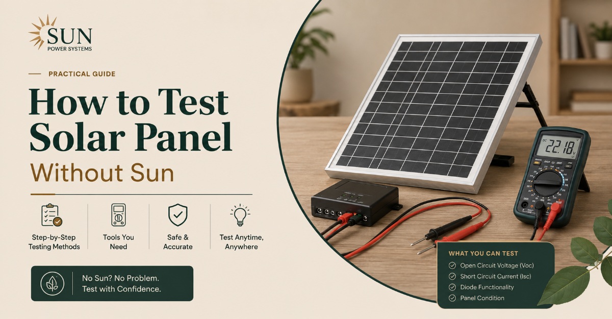
You can test a solar panel without sun by measuring its open-circuit voltage, checking current under a controlled artificial light source, and inspecting bypass diodes with the panel electrically isolated. Artificial-light testing confirms basic photovoltaic response, but it cannot reproduce the panel’s rated output unless a calibrated solar simulator supplies Standard Test Conditions.
Key facts at a glance
- A solar panel can show voltage indoors, but its current depends heavily on lamp intensity, spectrum, distance, and illuminated area.
- Open-circuit voltage is the safest first electrical test because the multimeter remains in voltage mode.
- A household LED lamp may produce a measurable voltage, while a 300-500 W halogen lamp generally produces a stronger response but also creates dangerous heat.
- A panel’s nameplate wattage cannot be validated accurately with an ordinary lamp and multimeter.
- A bypass-diode test checks protection components, not every cell, ribbon, solder joint, or micro-crack.
- Professional flash simulation and electroluminescence testing are required for calibrated performance and hidden-defect analysis.
What does testing a solar panel without sun mean?
Testing a solar panel without sun means either stimulating its photovoltaic cells with artificial light or checking its electrical components without generating photovoltaic power. The first approach measures real light-driven voltage and current. The second approach checks continuity, connector condition, and bypass-diode behavior.
Solar cells respond to photons across a broad range of wavelengths. Crystalline silicon cells commonly respond from roughly 300-1,100 nanometres, although response strength varies by cell design, glass, encapsulant, and infrared sensitivity. A lamp therefore may produce a reading without matching sunlight’s intensity or spectrum.
The U.S. Department of Energy explains the basic operating condition plainly: “Solar panels work best in full, direct sunlight.” Indoor testing is consequently a screening procedure, not a substitute for a rated outdoor performance test.
What can an indoor test prove?
An indoor test can establish whether a panel produces polarity-correct voltage, whether its output changes when light reaches the cells, and whether a severe open circuit exists. It can also identify visibly damaged connectors, failed bypass diodes, and some gross wiring faults.
An indoor test cannot reliably establish rated watts, conversion efficiency, annual energy yield, or the presence of every micro-crack. A 400 W panel that produces 20 V indoors has not necessarily failed, because current may be only a small fraction of its outdoor short-circuit current.
What tools and precautions are needed?
Use a digital multimeter rated for the panel’s maximum DC voltage, insulated test leads, suitable MC4 connectors, a nonflammable support, and a measured artificial light source. A clamp meter with DC capability is preferable for current because it avoids placing the meter directly across a live source.
Before starting, disconnect the solar panel from batteries, charge controllers, inverters, optimizers, and other panels. Cover the panel before disconnecting MC4 connectors if bright outdoor light is present, and never disconnect a PV connector under load unless the connector and equipment instructions explicitly permit it.
Before you start
| Item | Typical requirement | Why it matters |
|---|---|---|
| Test time | 10-30 minutes | Includes setup, voltage, current, and inspection |
| Difficulty | Basic electrical skill | Current measurement can short the panel |
| Multimeter | CAT III, 600 V or higher | Protects against unexpected DC voltage |
| Light source | 100-500 W halogen or strong LED array | Provides measurable indoor irradiance |
| Test leads | Insulated, shrouded probes | Reduces accidental terminal contact |
| Work surface | Dry, nonflammable, stable | Limits heat and connector movement |
| Extra protection | Eye protection and meter fuse | Helps manage arc and short-circuit risk |
Expert rule: Begin with voltage mode and leave the red lead in the voltage socket. Moving the lead to the amp socket before understanding the circuit is the most common way to create an accidental short circuit.
How does artificial light test photovoltaic cells?
Artificial light tests photovoltaic cells by supplying photons that create a voltage between the panel’s positive and negative terminals. The reading depends on light intensity, spectrum, angle, illuminated area, cell temperature, and the electrical load connected to the panel.
Sunlight at Standard Test Conditions has an irradiance of 1,000 W/m², a cell temperature of 25°C, and an air mass value of AM1.5 under IEC 60904 testing conventions. A room lamp usually supplies far less irradiance and illuminates the panel unevenly, so the panel may reach much lower current while retaining a moderately recognizable voltage.
Voltage changes logarithmically with irradiance, while short-circuit current changes approximately in proportion to irradiance over a useful operating range. That distinction explains why a panel can show a voltage near its normal range but deliver very little current indoors.
Which lamps work best?
A halogen lamp usually produces more useful near-infrared radiation and higher intensity than a normal household LED bulb, but its heat can damage the panel. A high-output LED array can also produce a reading when it supplies enough irradiance in wavelengths the silicon cells absorb; the claim that all LEDs are unsuitable is incorrect.
| Light source | Typical electrical input | Useful spectrum or limitation | Indoor test value | Main risk |
|---|---|---|---|---|
| Household LED bulb | 8-20 W | Visible spectrum, low irradiance | Small panels and polarity checks | Weak or uneven output |
| LED floodlight | 30-150 W | Broad white spectrum, limited infrared | Safer extended testing | Requires close, even placement |
| Halogen work lamp | 300-500 W | Broad visible and infrared output | Strong voltage and current response | Rapid glass and laminate heating |
| Incandescent bulb | 100-250 W | Broad spectrum, low efficiency | Small-panel response check | Heat and low usable irradiance |
| Solar simulator | Calibrated to 1,000 W/m² | Reference spectrum and uniformity | STC power measurement | High equipment cost |
A lamp’s electrical wattage is not the same as light irradiance at the panel. A 500 W halogen lamp may deliver a stronger local test than a 100 W bulb, but it still does not automatically reproduce 1,000 W/m² across the whole module.
How to test solar panel without sun with a multimeter
The safest household procedure is to measure open-circuit voltage first, then measure current only if the meter, leads, panel rating, and connection method are understood. Expect a response test, not a precise wattage certification.
Step 1: Read the panel nameplate
Record the module’s rated open-circuit voltage, short-circuit current, maximum-power voltage, maximum-power current, and rated power. Typical labels use the abbreviations Voc, Isc, Vmp, Imp, and Pmax.
For example, a nominal 100 W “12 V” module may have Voc around 22 V, Vmp around 18 V, Isc around 5.8 A, and Imp around 5.5 A. The phrase “12 V” describes battery-system compatibility, not a 12 V open-circuit measurement.
Checking Voc & Isc
Step 2: Isolate and inspect the panel
Disconnect all external equipment and inspect the glass, backsheet, junction box, cables, and MC4 connectors. Look for cracked glass, browning, delamination, melted plastic, loose leads, corrosion, and water entry.
Do not open a sealed junction box merely to perform a basic test. Opening it can compromise the enclosure and may void the warranty.
Panel Isolation Check
Step 3: Measure open-circuit voltage in darkness
Set the multimeter to DC voltage above the panel’s maximum expected voltage. Connect the red probe to positive and the black probe to negative, then cover the panel and record the dark reading.
A healthy isolated panel should normally read close to zero volts in darkness, although meter resolution, residual light, and connected electronics can create small values. If the panel is illuminated by a lamp, measure the polarity-correct voltage again.
Voltage Response Check
Step 4: Illuminate the panel evenly
Place the panel on a heat-resistant surface and position the lamp perpendicular to the cells. Start at least 50 cm away, run the lamp for 30-60 seconds, and monitor the glass and backsheet temperature.
A closer lamp can increase the reading but can also create a hot spot. Do not place a 300-500 W halogen lamp 20-30 cm from a full-size module unless the manufacturer or test procedure specifies thermal controls.
Illumination Consistency Check
Step 5: Measure short-circuit current carefully
Switch the meter off or disconnect the leads before changing from voltage to current mode. Move the red lead to the correct fused current socket, select DC amps, and confirm that the meter’s maximum current rating exceeds the panel’s Isc.
Connect the meter directly across the panel terminals for only a few seconds, then remove it. A DC clamp meter around one conductor is safer where the conductor and instrument support the expected current.
Current Measurement Check
Step 6: Calculate the limited indoor output
Approximate Test Power
Calculate approximate test power as:
| Panel label example | Outdoor STC rating | Typical indoor screening observation | Interpretation |
|---|---|---|---|
| Small 5 W panel | Voc 10 V, Isc 0.6 A | 6-10 V, 0.05-0.3 A | Light response may be measurable |
| 50 W module | Voc 22 V, Isc 3 A | 12-21 V, 0.05-0.8 A | Current varies strongly by lamp |
| 100 W module | Voc 22 V, Isc 5.8 A | 15-22 V, 0.1-1 A | Not an STC power test |
| 400 W module | Voc 37 V, Isc 13 A | 25-37 V, usually low current | Lamp may not cover the module |
| 12 V flexible panel | Voc 22 V, Isc 2-6 A | Voltage may appear normal | Inspect for hidden cell and ribbon damage |
These values are typical screening ranges, not pass-fail specifications. Lamp distance, optical area, panel technology, and meter burden voltage can change them substantially.
Can a multimeter test a solar panel in complete darkness?
A multimeter can test a solar panel in darkness for continuity-related faults, but resistance mode does not measure photovoltaic performance and diode mode usually cannot evaluate the whole module. The safe dark test is to inspect wiring and test accessible bypass diodes only after disconnecting every external circuit.
A full panel contains many series-connected cells, interconnect ribbons, and one or more bypass diodes. Its voltage-current behavior is not equivalent to one ordinary silicon diode. A handheld meter may lack enough test voltage to forward-bias a complete cell string, and resistance readings can be misleading.
How should bypass diodes be tested?
If the junction box provides accessible diode terminals, identify the diode circuit from the manufacturer’s wiring diagram. Use diode mode across the diode itself, not across the entire panel, and compare the reading with the diode datasheet.
A healthy silicon bypass diode often shows a forward drop near 0.2-0.7 V, depending on current and diode type, and an open circuit in reverse. Schottky diodes commonly read toward the lower part of that range. A short in both directions suggests diode failure, while an open circuit in both directions may indicate a failed diode or an incorrect test connection.
| Diode-mode result at accessible diode | Likely meaning | Recommended action |
|---|---|---|
| 0.2-0.7 V one way, OL reverse | Normal diode behavior | Reassemble and continue panel testing |
| Near 0 V both ways | Shorted bypass diode | Isolate and replace with rated part |
| OL both ways | Open diode or wrong terminals | Verify wiring and datasheet |
| Unstable reading | Poor probe contact or moisture | Clean, dry, and retest |
| Panel-wide diode reading only | Test point is incorrect | Do not diagnose the whole panel from it |
Never connect a battery to a panel in reverse to make it glow or heat. Electroluminescence equipment uses controlled forward current, current limiting, and suitable imaging; improvised reverse-current testing can damage cells, wiring, or the power supply.
What does a professional solar simulator or EL test show?
A solar simulator measures panel performance under a calibrated light pulse or continuous light source, while electroluminescence imaging reveals physical defects by driving the module electrically and capturing near-infrared emission. These are separate tests with different purposes.
IEC 60904-9 classifies solar simulators by spectral match, spatial non-uniformity, and temporal instability. A laboratory flash simulator can measure the I-V curve near reference conditions, including Voc, Isc, Vmp, Imp, fill factor, and maximum power.
EL testing is commonly performed by forward-biasing the module in darkness and using a sensitive camera. Dark cracks, inactive cell regions, broken fingers, and some solder or interconnect defects may appear as dark patterns. EL does not automatically predict the exact future power loss, and image interpretation requires trained comparison with module design and electrical data.
When is professional testing worth paying for?
Professional testing is justified for warranty disputes, commercial acceptance, suspected micro-cracks, insurance claims, production quality control, and panels whose outdoor performance is significantly below specification. It is rarely economical for a single inexpensive garden-light panel.
| Method | Typical equipment cost | Result | Typical duration | Best use |
|---|---|---|---|---|
| Basic multimeter test | $15-$60 | Polarity and approximate voltage | 5-15 minutes | Dead-panel screening |
| Lamp plus load test | $30-$200 | Relative voltage and current | 10-30 minutes | Small modules and comparison |
| DC clamp and I-V tools | $150-$2,000 | Field current and curve data | 15-45 minutes | Technician diagnosis |
| Flash solar simulator | $5,000-$100,000+ | Calibrated STC I-V curve | Seconds to minutes | Factory and acceptance testing |
| EL imaging system | $10,000-$50,000+ | Cell and interconnect defect image | 5-30 minutes | Warranty and quality analysis |
Which test should you choose?
Choose artificial-light voltage testing for a quick household answer, a controlled load test for useful relative comparison, bypass-diode testing for junction-box faults, and laboratory simulation or EL imaging for certified performance and hidden structural defects.
| User situation | First test | Avoid relying on | Escalate when |
|---|---|---|---|
| Used panel purchase | Voc and visual inspection | Indoor watts alone | Voc is zero or glass is damaged |
| RV or portable panel | Voc, Isc, and charge-controller input | Nominal “12 V” label | Controller reports persistent low input |
| Small 5-20 W panel | Strong LED or outdoor test | Weak room lighting | Load voltage collapses immediately |
| Roof-mounted array | Inverter diagnostics and qualified field test | Disconnecting live MC4s | Arc, insulation, or ground fault appears |
| Warranty claim | Photos, label data, outdoor I-V test | Uncalibrated lamp result | Output misses warranty threshold |
| Suspected micro-crack | EL imaging and thermal inspection | Resistance mode | Crack, hotspot, or intermittent output exists |
Why does a solar panel show voltage but no current?
A solar panel can show normal open-circuit voltage but almost no current when the test circuit is incomplete, the light is too weak, a connector is damaged, a meter fuse is blown, or a cell string has an internal interconnect fault. Voltage alone proves that some photovoltaic junctions are responding, not that the power path can carry load current.
First test the meter on a known DC source, then verify that the ammeter lead is in the correct socket and the current fuse is intact. Check MC4 polarity and connector seating. If the panel voltage collapses when a small known load is connected, suspect high resistance, cracked ribbons, or a weak cell string.
A bypass diode is not the default explanation for every zero-current result. A shorted bypass diode usually reduces voltage for the protected substring and can create heating; it does not universally produce normal voltage with exactly zero current.
What common mistakes produce false results?
The most damaging errors are using the wrong meter socket, overheating the laminate with a close halogen lamp, testing a connected battery system, and comparing indoor readings directly with nameplate STC values. Each error can produce either a false failure diagnosis or physical damage.
Common mistakes and corrections
- Using a current mode across a voltage source: Disconnect the probes before changing modes, then use a correctly fused current input.
- Treating a 12 V panel as a 12 V output device: Compare the reading with Voc, which may be 20-24 V.
- Assuming a weak LED proves panel failure: Increase irradiance, reduce distance safely, or test outdoors under stable conditions.
- Creating a lamp hot spot: Use a larger, more distant source and monitor temperature with an infrared thermometer.
- Testing only one illuminated cell area: A partial-area test does not represent a series module with bypass sections.
- Opening the junction box unnecessarily: Use external measurements first and preserve the enclosure seal.
Practitioner insight: A stable Voc with collapsing load voltage often points to a series-resistance or interconnect problem, while a low Voc across the whole module more often points to shading, a bypass path, wiring error, or a damaged cell substring.
What alternatives work when no lamp is available?
When no suitable lamp is available, use a known outdoor test during a later daylight period, a panel-specific I-V tracer, or the connected system’s diagnostic data. A flashlight can prove polarity and response on a small cell, but it cannot meaningfully test a full-size module.
For a portable panel, connect a manufacturer-approved charge controller and observe input voltage and charging current under a known battery state, while following the controller’s connection order. For a roof system, read inverter DC voltage, current, insulation, and fault codes without opening high-voltage connectors.
A phone flashlight is inadequate for most full-size modules because its illuminated area and optical power are tiny. A dark-room test can still be useful for comparing two identical small panels under the same lamp, distance, angle, and load.
How should test results be interpreted?
Interpret results against the panel’s electrical label, test conditions, and test method rather than against a universal indoor voltage percentage. Voc is primarily a response and wiring indicator; Isc is more sensitive to light intensity and exposed cell area; loaded voltage and current reveal whether the panel can deliver usable power.
Use the following decision sequence:
- Zero or reversed voltage: Check polarity, leads, connectors, meter mode, and complete darkness.
- Voltage rises under light: The cells have a photovoltaic response.
- Normal voltage but no current: Check meter fuse, current socket, load wiring, and high-resistance connections.
- Low voltage with stable light: Check shading, bypass diodes, substring faults, and series wiring.
- Voltage fluctuates: Check loose MC4 contacts, lamp movement, thermal changes, and intermittent ribbons.
- Output falls as the panel heats: Investigate temperature coefficient, lamp heat, hotspots, and damaged cells.
A typical crystalline-silicon module loses roughly 0.3-0.4% of voltage per degree Celsius above its reference cell temperature, although the exact coefficient appears on the datasheet. Artificial lamps can heat the glass quickly, so a decreasing voltage may reflect temperature rather than immediate cell failure.
FAQ
Can I test a solar panel with a regular light bulb?
You can test a small solar panel with a regular incandescent bulb, but the result will usually be limited because household bulbs provide low irradiance over a small area. Keep the bulb away from the panel, monitor heat, and measure DC voltage first. A measurable voltage confirms light response, not rated wattage.
Will a solar panel charge under an LED light?
A solar panel can charge under an LED light when the LED supplies sufficient optical intensity and suitable wavelengths, but charging current is usually very low. A high-output LED floodlight works better than a ceiling bulb. The panel’s response depends on LED spectrum, distance, illuminated area, and the charge controller’s startup voltage.
Can I test a solar panel with a battery?
Do not connect a battery directly to a solar panel for a basic health test. A battery can force damaging current, bypass normal regulation, and create sparks or reverse-current faults. Use a correctly rated solar charge controller or a professional I-V test instrument designed to control current and voltage.
How do I test a solar panel with a phone flashlight?
Place the phone flashlight close to a small individual cell or miniature module and measure DC voltage across the terminals. The method is useful for confirming polarity and basic response, but it cannot test the output of a full-size panel because the flashlight illuminates too little area at too low an intensity.
Can a damaged solar panel still produce voltage?
A damaged solar panel can produce voltage while delivering substantially reduced power. Cracked cells, broken fingers, degraded ribbons, delamination, and high-resistance solder joints may leave Voc present but reduce Isc or loaded output. Compare voltage and current under the same conditions, then use EL or thermal inspection for hidden defects.
How long should an indoor solar-panel test take?
A basic isolated voltage test takes 5-10 minutes, while voltage, current, load, connector, and temperature checks typically take 15-30 minutes. Professional flash simulation can measure an I-V curve in seconds, but setup, calibration, and reporting often take much longer.
The bottom line
The safest way to test a solar panel without sun is to isolate it, measure open-circuit DC voltage, illuminate it evenly with a controlled artificial source, and measure current only with correct meter protection. Compare results with Voc and Isc from the datasheet, not with the panel’s rated watts under Standard Test Conditions. For warranty-grade accuracy or hidden cracks, use calibrated I-V, EL, or solar-simulator testing.
How to test solar panel without sun is therefore a screening question first and a laboratory question second. A voltage response can identify a functioning photovoltaic junction, but only controlled irradiance and safe load testing can establish useful output.