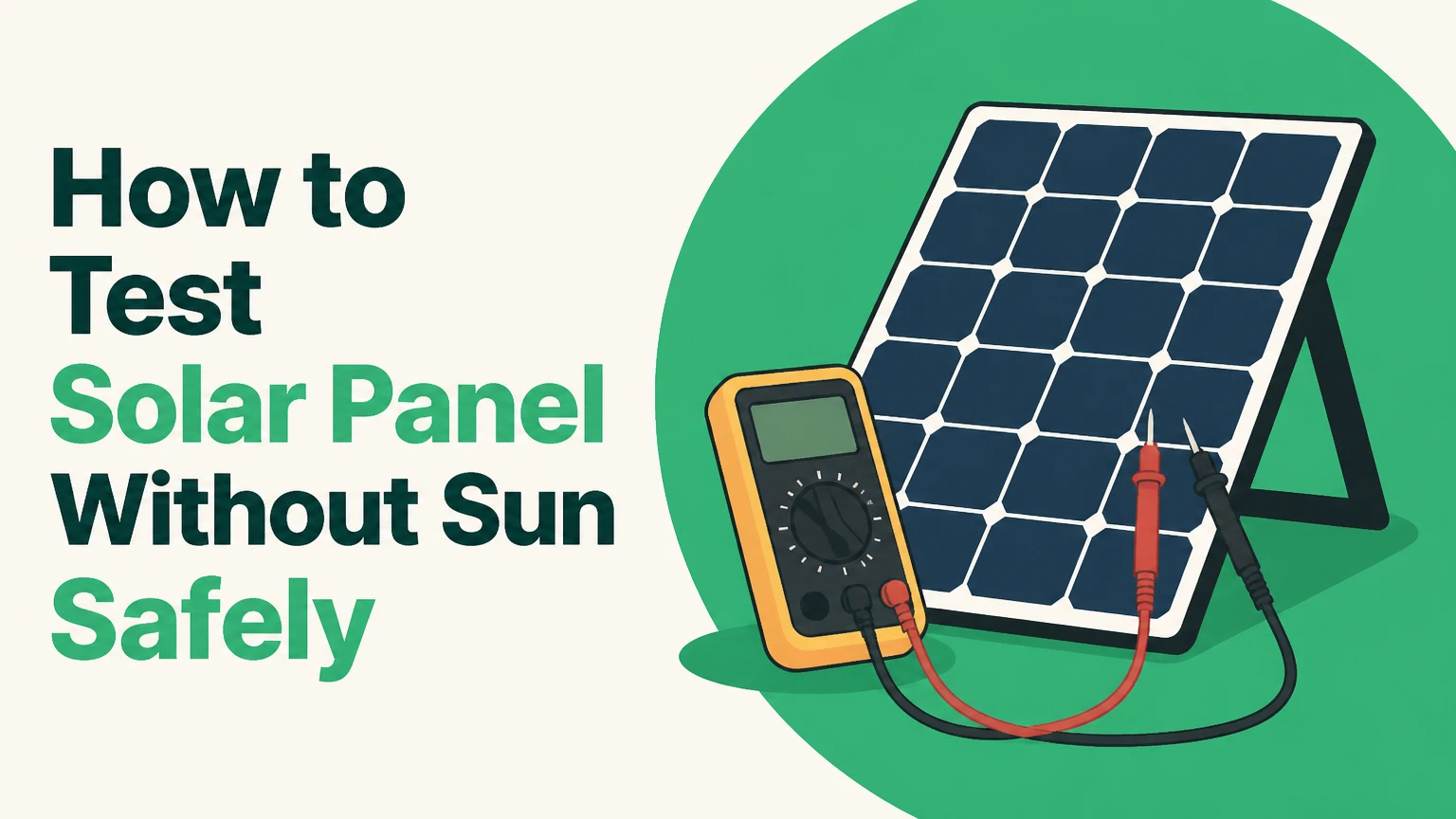
You can test a solar panel without sun by measuring its open-circuit voltage, checking current under a controlled light source, and inspecting bypass diodes and connectors. A multimeter can confirm basic electrical function indoors, but only a calibrated solar simulator can reproduce standard power output accurately.
Key Facts at a Glance
- A healthy photovoltaic panel can produce measurable voltage under artificial light, although current is usually far below its nameplate rating.
- Open-circuit voltage can appear normal while a panel has cracked cells, poor solder joints, or very low current capacity.
- A standard LED flashlight usually produces too little irradiance for a useful full-panel current test, but it may create a small voltage reading.
- A bypass-diode test can identify a shorted or open diode, but it cannot prove that every PV cell is healthy.
- Never connect a multimeter in current mode directly across a panel unless the meter, leads, fuse, and panel current rating are appropriate.
- An IEC solar simulator is required for meaningful STC power verification at 1,000 W/m², 25°C cell temperature, and an AM1.5 spectrum.
1. Can You Test a Solar Panel Without Sun?
Yes, a solar panel can be tested without direct sunlight, but the method determines what the result means. A digital multimeter can check polarity and open-circuit voltage in a few minutes, while an artificial lamp can demonstrate photovoltaic output; neither method reliably proves the panel will produce its rated wattage.
Solar cells respond to usable photons, not specifically to sunlight. Indoor light therefore can generate electricity when its spectrum and intensity overlap the cell’s response range. The practical problem is scale: indoor illumination is commonly hundreds of lux, whereas outdoor photovoltaic testing uses irradiance measured in watts per square metre and standardizes the reference at 1,000 W/m².
A panel may show close to its nominal voltage under weak light because voltage rises logarithmically with irradiance. Current responds much more directly to available light. That is why an indoor reading can show plausible voltage but almost no usable amperage.
The correct first objective is diagnosis, not performance certification. Ask whether the test must confirm electrical continuity, identify a dead section, estimate output, or verify a manufacturer rating.
2. Which No-Sun Testing Method Should You Use?
The best method depends on the fault you are trying to isolate. Use a multimeter for polarity and voltage, an artificial lamp for basic photovoltaic response, a diode-test function for junction-box components, and professional EL or flash testing for hidden defects and rated performance.
| Method | Primary result | Typical equipment | Typical time |
|---|---|---|---|
| Open-circuit voltage | Polarity and approximate string integrity | CAT-rated digital multimeter | 5-10 minutes |
| Artificial-light test | Basic light-to-electricity response | 300-500 W halogen lamp or strong broad-spectrum source | 10-20 minutes |
| Bypass-diode test | Shorted or open junction-box diode | Multimeter with diode mode | 5-15 minutes |
| Electronic-load test | Voltage and current under load | DC electronic load, shunt, or PV analyzer | 20-45 minutes |
| Electroluminescence imaging | Cracks, inactive cells, solder defects | DC supply and NIR-sensitive camera | 30-90 minutes |
| Solar simulator test | IV curve and STC-related performance | Calibrated Class AAA simulator | 1-2 hours including setup |
Artificial lamps: what actually works?
Halogen and incandescent lamps generally provide more infrared and visible energy than household LEDs, so they often produce a more noticeable response from crystalline-silicon cells. However, a 500 W lamp placed 40 centimetres from glass can heat the module quickly, create uneven illumination, and damage the encapsulant.
A broad-spectrum LED work light can also produce a measurable response if it illuminates the entire panel at sufficient intensity. The common claim that silicon cells cannot respond to LEDs is incorrect. The limiting factors are usually low irradiance, a small illuminated area, beam unevenness, and the lamp’s electrical power, not the word “LED” on the package.
| Light source | Likely panel response | Main limitation | Safe-use note |
|---|---|---|---|
| LED flashlight, 5-15 W | Millivolts to a few volts locally | Tiny illuminated area and low power | Do not treat a reading as a panel pass |
| Household LED bulb, 9-15 W | Small voltage, negligible useful current | Low irradiance at panel distance | Suitable only for a basic demonstration |
| LED work light, 50-150 W | Measurable voltage and small current | Spectrum and beam uniformity vary | Keep ventilation around the module |
| Halogen lamp, 300-500 W | Stronger voltage and current response | High radiant heat and uneven exposure | Use a stand, distance, and short intervals |
| Incandescent lamp, 100-300 W | Measurable response on small modules | Low efficiency and substantial heat | Do not place against the glass |
| Solar simulator | Reproducible IV curve | High equipment and calibration cost | Use trained personnel |
The strongest DIY result comes from illuminating the whole module evenly and measuring current through a known load. Lighting only one corner can leave most cell strings inactive, producing a misleading voltage or current result.
3. What Should You Do Before Connecting a Meter?
Disconnect the panel from batteries, charge controllers, inverters, microinverters, and parallel panels before testing. Inspect the backsheet, glass, junction box, cables, and connectors first, because cracked glass, exposed conductors, or water intrusion can make a low-voltage test unsafe.
Before You Start
| Requirement | Typical value |
|---|---|
| Test duration | 15-30 minutes for basic checks |
| Skill level | Beginner for voltage, intermediate for current |
| Minimum tool cost | $15-$40 for a suitable multimeter |
| Optional lamp cost | $25-$80 for a work light |
| Required meter category | CAT III 600 V DC preferred |
| Panel condition | Dry, isolated, and physically stable |
Wear eye protection and avoid testing damaged modules outdoors during damp conditions. Solar panels can produce hazardous DC voltage whenever light reaches them, and DC arcs do not extinguish as readily as AC arcs.
Read the label before testing. Record maximum-power voltage, open-circuit voltage, maximum-power current, short-circuit current, rated wattage, and the panel’s maximum system voltage. A “12 V” nominal panel may have a Vmp near 18 V and a Voc near 22 V, while a residential module may have a Voc above 45 V.
The National Electrical Code treats photovoltaic circuits as electrical systems requiring appropriate overcurrent protection, disconnecting means, and wiring practices; a homeowner should not open energized equipment or defeat installed protection.
4. Step 1: Inspect the Panel and Confirm Its Ratings
Place the panel face down on a clean, padded surface and photograph the label before removing any connectors. Look for cell cracks, browning, delamination, burned junction-box plastic, loose cables, corroded MC4 contacts, and broken glass.
Check each connector for a fully seated locking sleeve. Do not assume two connectors are electrically compatible because both resemble MC4 connectors; mating products from different manufacturers can create resistance, heating, or poor sealing.
Compare the label values with your test plan.
| Panel label value | Meaning | Example reading | Why it matters |
|---|---|---|---|
| Voc | Maximum unloaded panel voltage | 22.4 V | Voltage test reference |
| Vmp | Voltage at maximum power | 18.2 V | Load-test reference |
| Isc | Short-circuit current | 5.8 A | Meter and fuse requirement |
| Imp | Current at maximum power | 5.3 A | Electronic-load reference |
| Pmax | Rated maximum power | 96 W | Output comparison |
| Maximum system voltage | Permitted series voltage | 1,000 V DC | Shock and equipment risk |
You will know the step worked when you have recorded the label values and found no exposed conductor or active connection to another device.
Common mistake: treating Voc as the panel’s operating voltage. Voc is measured with no load and is normally higher than Vmp.
5. Step 2: Measure Open-Circuit Voltage Under Available Light
Set the multimeter to DC volts, choose a range above the panel’s maximum possible Voc, and connect the probes across the isolated positive and negative leads. Under an artificial lamp, compare the polarity and stability of the reading with the label’s Voc, but do not expect a normal nameplate result from weak indoor illumination.
Use the red probe on positive and the black probe on negative. If the meter shows a negative number, the leads are reversed or the panel’s connector polarity is not what you assumed. Confirm the connector pinout with a meter rather than relying on cable colour.
Under weak, uneven light, a healthy panel may produce a voltage that rises and falls as the lamp moves. A stable reading near zero suggests reversed assumptions, a broken connection, a severely shaded cell string, or an internal open circuit. A reading around half or one-third of expected voltage can indicate a failed section or a bypass diode conducting across part of the module, but the meter alone cannot identify which fault is present.
You will know the step worked when the polarity is correct and the voltage remains reasonably stable for 30 seconds with the lamp fixed in place.
Common mistake: placing a halogen lamp directly on the glass. Keep the lamp at least 50 centimetres away initially, monitor the glass by touch only after switching the lamp off, and stop if the module becomes uncomfortably hot.
6. Step 3: Measure Current Through a Load
Measure panel current through a known load rather than shorting the panel with an unsuitable meter. A 12 V automotive bulb, power resistor, or correctly rated DC electronic load provides a safer way to determine whether the panel can deliver current under artificial light.
The safest beginner arrangement is panel positive to the load positive, load negative to the meter’s current input if the meter and fuse are rated for the expected current, and meter common back to panel negative. Many meters cannot safely interrupt or carry the full Isc of a residential module.
If you use a multimeter for current, move the red lead to the fused high-current terminal, select the highest DC-current range, and make the connection only after switching off the lamp. Never rotate the meter from volts to amps while the probes remain connected across the panel. That action can create a short circuit and blow the meter fuse.
Indoor current may be a few milliamps or a fraction of an ampere, depending on lamp distance, illuminated area, spectrum, and panel size. A zero reading does not prove an open circuit if the light is too weak or the current path is incorrectly wired.
You will know the step worked when current changes predictably as the lamp is moved closer or farther away, while the panel remains cool and the meter stays within its fused range.
Common mistake: comparing indoor Isc directly with the nameplate Isc. The label value was obtained under defined irradiance and temperature conditions, not under a desk lamp.
7. Step 4: Check Bypass Diodes and Connectors
Test bypass diodes only after isolating the module and confirming that the junction box can be opened without breaking its seal. A healthy diode commonly shows a forward drop around 0.2-0.7 V and an open-circuit indication in reverse bias, but readings vary by diode type and by the connected cell circuit.
The exact procedure depends on the junction-box design. Some diodes are soldered, some are clipped into holders, and some are integrated into a sealed assembly. Do not pry open a sealed box on a module that may be returned under warranty.
With the multimeter in diode mode, place the red probe on the diode anode and the black probe on the marked cathode. Record the forward reading, reverse the probes, and record the reverse result. A near-zero reading in both directions suggests a shorted diode; an open reading in both directions suggests an open diode, poor contact, or a diode still affected by the surrounding circuit.
| Diode result | Likely meaning | Next action |
|---|---|---|
| 0.2-0.7 V forward, OL reverse | Diode behaves normally | Continue panel-level testing |
| 0.00-0.05 V both directions | Shorted diode or parallel circuit path | Isolate diode and retest |
| OL both directions | Open diode, bad probe contact, or circuit interaction | Inspect holder and isolate |
| Unstable reading | Corrosion, loose terminal, or poor probe contact | Clean only de-energized contacts |
| Normal diode, low panel voltage | Cell-string or interconnect fault | Use load, IV, or EL testing |
A bypass diode protects a shaded or damaged cell group by allowing current to bypass that section. A shorted diode can reduce module voltage, while an open diode may remove protection without necessarily causing zero Voc.
You will know the step worked when the diode result is repeatable with firm probe contact and the junction box remains mechanically intact.
Common mistake: concluding that a normal diode proves a normal panel. The diode is one component in the junction box, not a test of the silicon cells.
8. Which Method Gives the Most Reliable Diagnosis?
A solar simulator gives the most reliable performance result, an IV tracer gives the most useful field curve, and electroluminescence imaging reveals defects that voltage and current checks can miss. Basic artificial-light testing is appropriate for screening, not for warranty-grade acceptance.
| Diagnostic goal | Best method | Result quality | Typical cost |
|---|---|---|---|
| Confirm polarity | DC multimeter | High for isolated wiring | $15-$40 |
| Find a shorted bypass diode | Diode tester plus isolation | Moderate to high | $15-$80 |
| Check current under load | Electronic load or PV analyzer | Moderate to high | $100-$1,500 |
| Locate microcracks | EL imaging | High with trained interpretation | $500-$5,000 |
| Verify rated power | Calibrated solar simulator | Highest | $100-$500 service fee |
| Compare outdoor output | Irradiance meter plus IV test | Moderate | $150-$1,000 |
How does electroluminescence reveal hidden damage?
Electroluminescence testing injects controlled forward current into a dark, isolated module, causing the silicon cells to emit near-infrared light. A suitable camera records dark regions and line breaks that can indicate microcracks, inactive areas, broken fingers, poor soldering, and some degradation patterns.
EL is not a beginner substitute for a multimeter. The power supply must be selected for the module’s electrical characteristics, the panel must be safely isolated, and the operator must understand polarity and current limiting. Applying uncontrolled reverse voltage or excessive forward current can destroy cells.
Why is a solar simulator different?
A solar simulator controls irradiance, spectral distribution, uniformity, and timing so that a panel’s current-voltage curve can be compared with standardized conditions. IEC 61215 qualification uses defined environmental and performance tests, while a flash tester measures output quickly under a controlled light pulse.
A simulator does not repair a module or automatically explain every fault. It reports performance under its test conditions. Temperature, stabilization, calibration, and measurement uncertainty still matter.
9. Can You Test a Panel on a Cloudy Day Instead?
Yes, outdoor testing on a bright overcast day is usually more representative than a household lamp, provided you measure irradiance and account for diffuse light. A solar irradiance meter and a PV analyzer can produce a useful comparison, whereas a voltage-only reading cannot establish panel wattage.
Mount the panel unobstructed, keep the face clean, record module temperature, and measure irradiance at the same plane as the panel. Compare current more readily than voltage because current changes more strongly with irradiance. Do not use a simple proportional calculation as a certification result, because spectrum, angle of incidence, temperature, and diffuse-light conditions also affect output.
Outdoor testing has its own complications. Passing clouds can change irradiance during the measurement, wind can cool the cells, and a bifacial panel may receive rear-side light that a basic test does not capture.
10. What Do Common Test Results Mean?
Test results must be interpreted with the test conditions attached. A low current under a weak lamp is expected, while zero voltage under a bright, evenly distributed source is much more suspicious.
| Symptom | More likely causes | Confirmation test | Correct response |
|---|---|---|---|
| Zero volts in bright light | Reversed leads, open connector, internal break | Polarity and continuity checks | Stop and inspect wiring |
| Normal Voc, almost zero load current | Weak light, broken interconnect, high-resistance joint | Stronger uniform light and load test | Seek IV tracing if repeated |
| About half expected voltage | Failed cell section or conducting bypass diode | Isolated diode and IV test | Replace diode only if confirmed |
| Voltage fluctuates when cable moves | Loose crimp, corroded connector, damaged lead | Wiggle test while unpowered, visual inspection | Replace connector or cable |
| Voltage rises but collapses under load | High series resistance or cracked connection | Several load points | Professional IV diagnosis |
| One area is hot | Resistive fault, junction-box issue, or shading | Thermal camera under safe operating light | Disconnect and inspect |
An exact 0.0 A reading under a small lamp is not proof of an internal open circuit. The lamp may illuminate too little area, the meter may be in the wrong terminal, or the load may be connected incorrectly.
A normal Voc with poor current is a particularly important warning. Voltage can survive partial circuit damage, while current requires a continuous path through the active cell strings and interconnects.
11. What Changes for Special Situations?
Testing a used panel before purchase
Ask for the label photograph, serial number, warranty status, and an outdoor IV or load result. Inspect for delamination, backsheet chalking, glass cracks, yellowing, junction-box burns, and connector replacement. A seller’s claim that the panel “shows voltage” is insufficient because Voc does not establish useful power.
Testing a small 5 V or 12 V panel
A small panel can be tested with a low-power resistor or USB load, but select the load from the panel’s rated current. For example, a nominal 6 V, 3 W panel has an approximate operating current of 0.5 A, so a load near 12 ohms would draw roughly that current at its rated voltage, subject to actual conditions.
Testing a bifacial module
Measure front and rear illumination separately when possible. A bifacial module can produce extra current from reflected rear-side light, so indoor front-only testing may understate its outdoor performance.
Testing a panel connected to an inverter
Do not probe AC or DC terminals casually. Shut down according to the manufacturer’s procedure, verify isolation with an approved meter, and use an electrician for rooftop strings, high-voltage batteries, or equipment that remains energized from multiple sources.
Common Mistakes and How to Fix Them
- Using a flashlight as a pass/fail test: A flashlight may prove photon response in one small area but cannot illuminate the module evenly. Use a load and a broad, stable source instead.
- Leaving a halogen lamp close to the glass: Heat can damage encapsulant and accelerate local thermal stress. Increase distance, shorten exposure, and use an infrared thermometer when available.
- Shorting a large module through a cheap meter: The meter fuse may rupture, the leads may overheat, or an arc may occur. Use a properly rated shunt or electronic load.
- Opening a sealed junction box immediately: The action can void a warranty and introduce moisture. Photograph the defect and consult the manufacturer first.
- Treating voltage as wattage: Power equals voltage multiplied by current, and current must be measured under a defined load.
- Testing only one connector: A connector can pass a no-load voltage yet fail under current because of corrosion or a high-resistance crimp.
A useful practitioner rule is to repeat any surprising result with a second setup. Change the lamp position, use a known load, verify the meter with a battery, and inspect connector polarity before declaring a panel dead.
FAQ
Can a solar panel charge a battery under a room light?
A solar panel may charge a very small battery under a strong, close artificial source, but ordinary room lighting usually provides too little current for practical charging. A charge controller can also consume more power than the panel produces indoors, so a voltage reading does not mean useful battery charging will occur.
How long should a halogen lamp shine on a solar panel?
Use short test intervals of about 30-60 seconds, then switch the lamp off and allow the module to cool. The correct duration depends on distance, lamp wattage, ventilation, and glass temperature. Stop immediately if the panel becomes excessively hot, develops an odor, or shows discoloration.
Can a multimeter test a solar panel by itself?
A multimeter can test polarity and open-circuit voltage by itself, but current requires a properly rated circuit or load. A voltage-only test cannot detect every cracked cell, high-resistance connection, or power loss, so a complete diagnosis needs at least one loaded measurement.
What voltage should a 12 V solar panel show indoors?
A nominal 12 V crystalline-silicon panel commonly has a label Voc around 20-24 V and Vmp around 17-20 V, although exact values vary by design. Indoors, voltage may be lower and unstable. Compare the result with the panel’s own label rather than a generic 12 V expectation.
Is a solar panel dead if it reads zero amps?
Zero amps does not automatically mean the panel is dead. Confirm that the artificial light is strong and evenly distributed, the current range and fused lead are correct, the load is connected, and the connectors have continuity. If voltage is present but loaded current remains zero, arrange an IV or professional inspection.
Should you replace a bypass diode yourself?
Replace a bypass diode only when the module design permits access, the exact diode rating is known, and the panel is isolated and out of warranty. Many junction boxes are sealed, and an incorrect diode can create overheating or protection failure. Manufacturer service instructions should take priority.
The Bottom Line
How to test solar panel without sun depends on the decision you need to make. Use a multimeter for polarity and Voc, a controlled lamp and load for basic indoor output, diode mode for junction-box checks, and an IV tracer, EL camera, or calibrated solar simulator for professional diagnosis.
Artificial light can confirm that a panel responds electrically, but it cannot reproduce standard sunlight power by default. Treat low indoor current as a limitation of the test until irradiance, illumination area, wiring, and load have been verified. Treat zero voltage, unstable readings, damaged insulation, or overheating as reasons to stop and investigate safely.