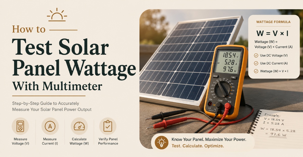
To test solar panel wattage with a multimeter, measure the panel’s open-circuit voltage (V_{oc}) and short-circuit current (I_{sc}), then compare those readings with the label values. A multimeter cannot directly measure true maximum power (P_{max}) unless the panel is connected to a controlled load that produces (V_{mp}) and (I_{mp}).
Key facts at a glance
- Solar panel wattage at maximum power is calculated as (P_{max}=V_{mp}\times I_{mp}).
- A voltage test places the multimeter in parallel across the disconnected panel.
- A current test places the multimeter in series with the panel and creates a near-short circuit.
- Never connect a multimeter in current mode directly across a battery or another live voltage source.
- A fixed 0.75 correction factor gives only a rough estimate, not a certified power measurement.
- Standard Test Conditions use 1,000 W/m² irradiance, 25°C cell temperature, and AM1.5 spectrum.
What can a multimeter actually measure?
A standard digital multimeter can measure a solar panel’s (V_{oc}) and, if correctly fused and rated, its (I_{sc}). Those two readings reveal whether the panel is producing voltage and current, but they do not reproduce the loaded operating point used for the factory wattage rating.
Solar modules have a nonlinear current-voltage relationship. Current remains relatively stable across part of the voltage range, then falls sharply near the open-circuit voltage. The highest product of voltage and current occurs at the maximum power point, abbreviated MPP.
The three important electrical points are:
| Measurement | Meaning | Typical relationship to rating |
|---|---|---|
| (V_{oc}) | Voltage with no external load | Usually higher than (V_{mp}) |
| (I_{sc}) | Current with the output shorted | Usually slightly higher than (I_{mp}) |
| (P_{max}) | Maximum power under a controlled load | Factory wattage rating |
| MPP | Operating point where voltage-current product peaks | Defined by (V_{mp}) and (I_{mp}) |
The formula (V_{oc}\times I_{sc}) overstates usable power because the panel cannot produce both values at the same time. The panel has zero power at (V_{oc}), because current is zero, and zero power at (I_{sc}), because voltage is zero.
Why does the factory wattage differ from a multimeter estimate?
Factory wattage is measured under Standard Test Conditions, or STC. IEC 61215 testing uses 1,000 W/m² irradiance, a 25°C cell temperature, and an air-mass 1.5 reference spectrum. Outdoor testing rarely reproduces all three conditions simultaneously.
A warm module normally produces lower voltage. The temperature coefficient printed on the datasheet often falls near -0.25% to -0.40% per degree Celsius for crystalline silicon power, although the exact value depends on the module. A panel with cells at 65°C can therefore lose roughly 10% to 16% of voltage-related power compared with its 25°C reference.
Irradiance mainly changes current. Temperature mainly changes voltage. This distinction helps identify faults instead of blaming every low reading on the same cause.
What should you prepare before testing?
Before testing, gather the panel datasheet, a correctly rated digital multimeter, insulated test leads, and a way to expose the module to unobstructed sunlight. Disconnect the panel from batteries, charge controllers, inverters, and parallel panels before taking standalone readings.
Before You Start
- Typical time: 10-20 minutes, including setup and repeat readings
- Difficulty: Basic electrical testing, with high consequences for incorrect current-port use
- Tools: Digital multimeter, rated probes, panel datasheet, insulated gloves, eye protection
- Meter requirement: DC voltage range above expected (V_{oc}), DC current range above expected (I_{sc})
- Best conditions: Clear sky, minimal shading, panel aimed directly at the sun
- Prerequisite: Confirm the panel is isolated and identify positive and negative conductors
Meter safety category matters. A CAT III or CAT IV rating applies to specified electrical environments, but it does not automatically mean the instrument is suitable for every DC photovoltaic string. Check the meter’s maximum DC voltage, current, interrupt rating, and fuse specification.
How to test solar panel wattage with multimeter
Testing takes four core steps: record the nameplate data, measure open-circuit voltage, measure short-circuit current only when the meter is suitable, and compare the results with the rated maximum-power values. Sun intensity, panel temperature, shading, and meter limitations determine the quality of the conclusion.
Step 1: Record the panel’s rated values
Reading the Panel Label
Read the label on the rear junction box or the manufacturer datasheet. Record Pmax, Voc, Isc, Vmp, Imp, the maximum system voltage, and the temperature coefficients if available.
Do not confuse nominal battery-system voltage with measured panel voltage. A panel sold as “12 V” commonly has a Vmp near 17–18 V and a Voc near 21–22 V. A “24 V” module commonly has a Vmp near 34–36 V and a Voc near 42–44 V.
| Panel description | Typical Vmp | Typical Voc | Common use |
|---|---|---|---|
| 12 V nominal, 50 W | 17.5–18.5 V | 21–23 V | Small battery systems |
| 12 V nominal, 100 W | 17.5–18.5 V | 21–23 V | RV and portable systems |
| 24 V nominal, 200 W | 34–37 V | 42–45 V | Larger off-grid systems |
| Modern residential module, 400 W | 30–42 V | 38–50 V | Grid-connected arrays |
These are typical ranges, not acceptance limits. The manufacturer’s label controls the comparison.
Step 2: Measure open-circuit voltage
Measuring Open-Circuit Voltage
Set the multimeter to DC voltage, connect the black lead to COM, and connect the red lead to the voltage-resistance port. Select a range above the expected Voc, then place the probes across the isolated panel output.
- Disconnect the panel from every load and controller.
- Position the panel in direct, unobstructed sunlight.
- Touch the red probe to positive and the black probe to negative.
- Read the stable voltage after several seconds.
- Reverse the probes only if you need to confirm polarity.
A negative display indicates reversed probe polarity, not necessarily a damaged panel. A zero or very low reading in strong sun indicates a disconnected conductor, damaged junction box, severe shading, failed bypass component, or internal cell fault.
Step 3: Measure short-circuit current only when appropriate
Measuring Short-Circuit Current
A solar panel current test requires the meter to become part of the circuit. The current jack has a very low resistance path, so connecting the meter in current mode across a voltage source creates a short circuit.
Use the highest DC current range first. Move the red lead to the fused high-current port, usually marked 10 A or 20 A, and verify that the meter’s continuous current rating exceeds the panel’s expected Isc. Connect the meter in series across the isolated panel output, not across a battery or controller.
- Confirm the high-current fuse is installed and intact.
- Set the dial to the highest DC amperage range.
- Connect the black lead to panel negative.
- Connect the red high-current lead to panel positive.
- Read the current promptly.
- Disconnect the circuit, then return the red lead to the voltage port.
Do not deliberately create a visible spark. A spark can damage MC4 contacts, ignite flammable gas near batteries, or create an arc that persists at higher photovoltaic string voltages. For a small single panel, a brief current reading may be acceptable when the meter and wiring are correctly rated, but many technicians prefer an inline PV meter or controlled load.
Step 4: Calculate and interpret the result
Physically Meaningful Power
The physically meaningful power calculation is:
For factory-rated output, use:
For example, a 100 W module labeled Vmp = 18.2 V and Imp = 5.49 A has:
If the meter reads Voc = 21.8 V and Isc = 5.8 A, multiplying those values gives 126.4 W. That is not the panel’s output because the readings occur at different operating points.
A rough field estimate sometimes uses:
How accurate is a multimeter wattage test?
A multimeter-only test is useful for fault screening, but it is not an accurate measurement of rated wattage. Voltage and current readings taken at different electrical conditions cannot establish the module’s maximum power point.
| Test approach | What it measures | Typical accuracy or limitation | Best use |
|---|---|---|---|
| (V_{oc}) test | Voltage with no load | Often within meter resolution, but temperature-sensitive | Detect open circuits and polarity faults |
| (I_{sc}) test | Current at near-zero voltage | Limited by irradiance, fuse, leads, and meter burden voltage | Detect severe current loss |
| (V_{oc}\times I_{sc}\times0.75) | Rough estimated power | Commonly uncertain by 15-30% or more outdoors | Quick screening only |
| Electronic load sweep | Voltage-current power curve | Instrument-dependent, often far better than a basic meter | Determine (V_{mp}), (I_{mp}), and (P_{max}) |
| Solar analyzer with irradiance sensor | Corrected PV performance | Professional field verification | Commissioning and warranty evidence |
The largest practical uncertainty is usually irradiance, not the last decimal place on the multimeter. A cloud edge can briefly increase irradiance through reflection, while thin cloud or haze can reduce current without making the sky appear dark.
A useful practitioner rule is to repeat the test three times over several minutes and record panel temperature, sky condition, orientation, (V_{oc}), and (I_{sc}). A single reading is a clue. A repeatable pattern is evidence.
Which tools measure actual solar panel watts?
A controlled load or solar analyzer measures actual operating wattage more directly than a basic multimeter. The tool must allow the panel to operate at a voltage and current pair, then calculate (V\times I) while the load changes.
| Tool | Typical current range | Typical cost range | Measurement result | Main limitation |
|---|---|---|---|---|
| Basic digital multimeter | 10-20 A | $15-$60 | (V_{oc}), (I_{sc}) | No maximum-power sweep |
| Inline PV power meter | 10-30 A | $25-$120 | Live voltage, current, watts | Accuracy and connector ratings vary |
| Electronic DC load | 5-40 A | $80-$400 | Load curve and power | Requires correct voltage and heat handling |
| PV I-V curve tracer | 10-30 A or higher | $500-$5,000+ | (V_{mp}), (I_{mp}), (P_{max}) | Professional cost and setup |
| DC clamp meter | 40-600 A | $60-$500 | Current without disconnection | Often poor resolution at low panel current |
An MPPT tester or I-V curve tracer is the best choice when the question is whether a 400 W module actually produces near its rated maximum. An inline meter is more practical for a portable 100 W panel, but its displayed wattage may represent the connected load rather than the module’s theoretical maximum.
A clamp meter is convenient for installed arrays, yet ordinary clamp meters may not resolve 1-5 A accurately. Confirm that the model measures DC current, not only AC current.
What readings indicate a faulty panel?
Fault diagnosis works best when voltage and current are interpreted together. Low current with normal voltage points toward shading, dirt, connector resistance, cell damage, or irradiance loss, while low voltage points toward series-string or bypass-diode problems.
| Reading pattern | Likely cause | Immediate check | Probable interpretation |
|---|---|---|---|
| (V_{oc}) near label, (I_{sc}) near zero | Shading, broken conductor, severe cell damage | Inspect cells, cables, MC4 connectors | Current path is compromised |
| (V_{oc}) near zero | Reversed lead, open junction, failed connection | Check polarity and continuity of external cables | Voltage path is interrupted |
| Both values near half rating | Partial string or bypass-diode issue | Compare under full sun, inspect junction box | One series section may be bypassed |
| Normal (V_{oc}), low loaded watts | High resistance, hot module, weak load | Check connectors, temperature, load voltage | Open-circuit test hides the defect |
| Intermittent readings | Loose connector, cracked solder, cable movement | Wiggle external cable carefully, inspect terminals | Mechanical or contact fault |
Do not open a sealed junction box unless the manufacturer permits service and the panel is isolated. Bypass diodes can fail short or open, but diagnosing them inside a live module introduces shock, arc, and warranty risks.
Partial shading deserves special attention. Many modules contain series-connected cell groups, so a shadow across one group can force bypass-diode behavior and reduce power far more than the shaded area suggests. A small leaf can therefore cause a large current or power loss under load.
Why are outdoor readings lower than the label?
Outdoor readings are lower than the nameplate when irradiance is below 1,000 W/m², cells are hotter than 25°C, the sun is not perpendicular to the module, or the test circuit adds resistance. The label is a standardized reference, not a guaranteed midday output in every location.
Panel orientation affects incident irradiance. For a flat panel, sunlight at a steep angle travels through more atmosphere and strikes less active area, reducing current. Keep the module face aimed toward the sun and remove nearby shadows, including shadows from the meter leads.
Temperature affects voltage more strongly than current. A module that feels hot may show a normal (I_{sc}) but a reduced (V_{oc}), while a dirty or shaded module often shows a stronger current reduction.
The National Renewable Energy Laboratory’s PVWatts model accounts for irradiance, temperature, system losses, and other environmental conditions because nameplate DC capacity alone cannot predict field energy production. That same principle applies to a handheld test: compare like with like, and record conditions.
What safety mistakes must you avoid?
The most dangerous mistake is using the current setting across a voltage source. A photovoltaic module can deliver enough current to damage a multimeter, melt a probe lead, or create an arc, and series-connected panels can reach hazardous DC voltages even when each individual module appears modest.
Follow these rules:
- Verify the maximum panel and string (V_{oc}) before connecting the meter.
- Use probes with intact insulation and correctly rated connectors.
- Keep the red lead in the voltage port unless a current test is specifically planned.
- Never measure current across a battery, charge controller output, or inverter terminal.
- Do not exceed the meter fuse, lead, connector, or panel current rating.
- Cover the panel or disconnect its conductors before changing wiring.
- Keep batteries and flammable vapors away from intentional short-circuit tests.
- Stop if a lead, connector, fuse, or meter becomes warm.
- Use a qualified electrician for rooftop arrays or high-voltage strings.
Solar modules remain energized in daylight. Disconnecting an inverter does not necessarily make every PV conductor safe, particularly on arrays wired in series.
How do you test different panel situations?
Testing a 12 V nominal panel
A 12 V nominal panel commonly shows approximately 17-18.5 V at (V_{mp}) and 21-23 V at (V_{oc}). A reading near 12 V is not automatically correct, because 12 V describes the battery system the panel is intended to charge.
Test the panel disconnected from the battery. A battery-connected reading may be held near battery voltage by the charge circuit and cannot confirm open-circuit performance.
Testing a 24 V nominal panel
A 24 V nominal panel commonly shows about 34-37 V at (V_{mp}) and 42-45 V at (V_{oc}). Set the meter above the expected open-circuit voltage, and allow additional margin if several modules are connected in series.
For a series string, add the module (V_{oc}) values for a conservative maximum estimate, then apply the cold-temperature correction from the datasheet. Cold weather raises (V_{oc}), which can exceed the controller’s maximum input voltage.
Testing a portable folding panel
Portable panels often include a regulator, USB converter, or proprietary connector. Measure directly at the panel output before the regulator if possible, because the USB output may be limited to 5 V and its current-control circuit changes the result.
Do not assume a portable panel’s advertised wattage equals USB output wattage. A 100 W folding module may deliver substantially less through a small converter, cable, or power station input limit.
Common mistakes and how to fix them
The meter reads zero volts
Check that the panel is illuminated, the probes contact the conductive terminals, and the meter is set to DC volts. Confirm polarity and inspect the MC4 connectors for a pushed-back pin or broken cable.
The voltage is normal but current is very low
Remove every shadow, clean the surface, inspect connectors, and repeat the test with the panel aimed directly at the sun. If current remains low while (V_{oc}) is normal, inspect for cracked cells, delamination, junction-box damage, or a high-resistance connection.
The meter fuse blows
The red lead was probably left in the current jack, or the current range was connected across a voltage source. Replace the fuse only with the manufacturer-specified type and rating. Do not bridge the fuse with wire.
The result is far below rated watts
Record irradiance conditions and panel temperature before condemning the module. A hot panel under hazy sunlight can legitimately produce much less than its STC rating, but a repeatable loss under strong sun requires connector, shading, diode, and cell inspection.
The calculated value exceeds the label
That result usually comes from multiplying (V_{oc}) by (I_{sc}), which combines two values the panel cannot produce simultaneously. Use (V_{mp}\times I_{mp}), or measure the maximum-power point with a controlled load.
FAQ
Can I test a solar panel while it is connected to a battery?
You can measure system voltage while a panel is connected to a battery, but that is not an open-circuit panel test. Do not place a multimeter in current mode directly across the battery. Isolate the panel first when measuring (V_{oc}) or (I_{sc}).
What multimeter setting tests a solar panel?
Use the DC voltage setting, marked (V) with a straight-line symbol, for (V_{oc}). Use the DC current setting, marked A with a straight-line symbol, only for a correctly rated series current test. Start at the highest range and verify lead placement before connection.
How many watts should a 100 W solar panel produce?
A 100 W panel reaches approximately 100 W only near its STC maximum power point. Outdoor output commonly falls below that value because cell temperature, irradiance, angle, wiring, controller efficiency, and load voltage differ from laboratory conditions. A multimeter-only estimate cannot prove exactly 100 W.
Can I test a solar panel indoors?
Indoor testing under household lighting is not a valid output test. Artificial lamps usually provide far less irradiance and a different spectrum than sunlight, so the panel may show voltage but produce very little current. Use direct, unobstructed sunlight for diagnostic measurements.
Is a solar panel supposed to spark during a current test?
A spark is not a normal testing requirement and should not be deliberately produced. Connect the correctly rated circuit carefully, avoid flammable surroundings, and use an inline PV tester or controlled load when repeated current measurements are needed.
How do I test a solar panel without disconnecting MC4 connectors?
Measure voltage at an accessible parallel test point only if the point is correctly rated and the circuit condition is understood. For installed strings, use a DC clamp meter or PV analyzer. Do not force probes into sealed MC4 connectors, because poor contact can create resistance and arc damage.
The Bottom Line
A multimeter can verify a solar panel’s voltage and current health, but it cannot directly prove the panel’s rated wattage from (V_{oc}) and (I_{sc}). Measure the isolated panel in sunlight, compare both readings with the nameplate, and use (V_{mp}\times I_{mp}) or a controlled I-V test for real maximum power. Follow these limits whenever you test solar panel wattage with multimeter.