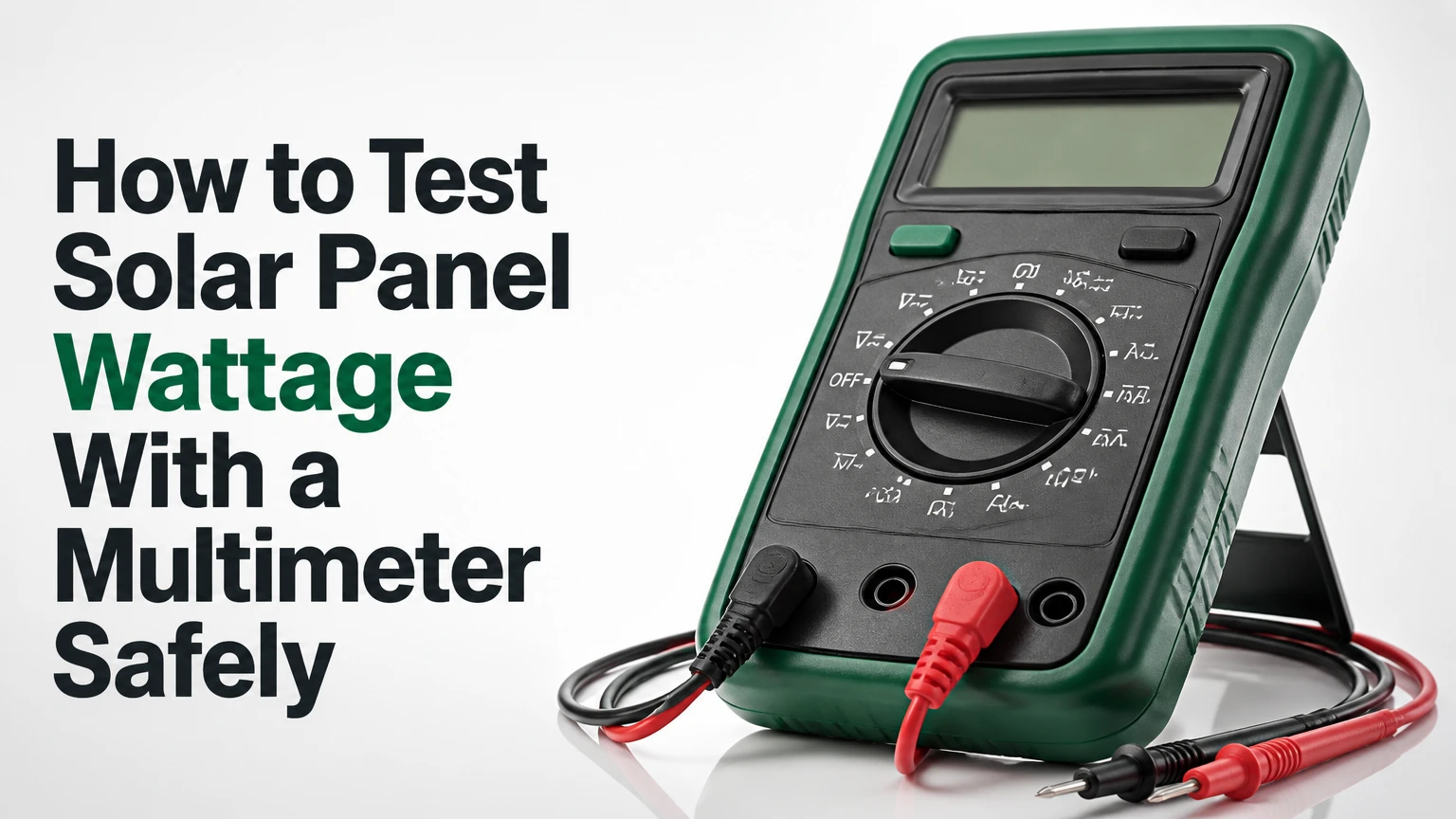
To test solar panel wattage with a multimeter, measure DC voltage and current, then calculate power as (P=V\times I). Measure open-circuit voltage and short-circuit current to check basic panel condition, but use a load, charge controller, or solar watt meter to measure actual operating watts because (V_{oc}\times I_{sc}) does not equal the panel’s true maximum power.
Key Facts at a Glance
- A digital multimeter measures voltage or current, not wattage directly.
- A panel’s rated wattage is (P_{max}=V_{mp}\times I_{mp}), not (V_{oc}\times I_{sc}).
- Open-circuit voltage is measured with the panel disconnected from every load.
- Short-circuit current requires the meter to become part of the circuit through its fused high-current input.
- Standard Test Conditions use 1,000 W/m² irradiance, 25°C cell temperature, and a defined reference spectrum.
- A loaded voltage-current measurement gives a more meaningful wattage result than a calculated open-short estimate.
What Does Solar Panel Wattage Mean?
Solar panel wattage is the electrical power a photovoltaic module can deliver at a specified operating point. Manufacturers identify that point as maximum power, or (P_{max}), using the voltage at maximum power, (V_{mp}), and current at maximum power, (I_{mp}).
The fundamental equation is:
[ P\text{ (watts)}=V\text{ (volts)}\times I\text{ (amps)} ]
For example, a module producing 18.2 V and 5.5 A under load is delivering approximately 100.1 W. A 100 W label does not mean the panel will produce 100 W in every outdoor test, because irradiance, cell temperature, orientation, shading, wiring, and the connected load all change the operating point.
PV Education describes the maximum power point as the point on the current-voltage curve “where the product of current and voltage is greatest.” That distinction matters because the highest voltage and highest current occur under different conditions.
Which panel specifications should you record?
Record the four values shown on the manufacturer label before connecting the multimeter. The label may be on the rear junction box, frame, datasheet, or portable-panel controller.
| Specification | Meaning | Typical value on a 100 W crystalline panel |
|---|---|---|
| (P_{max}) | Rated maximum power at STC | 100 W |
| (V_{oc}) | Voltage with no load connected | 21.6 V |
| (I_{sc}) | Current when output is shorted | 6.1 A |
| (V_{mp}) | Voltage at maximum power | 18.0 V |
| (I_{mp}) | Current at maximum power | 5.56 A |
The product of (V_{mp}) and (I_{mp}) should approximately equal the rated wattage. The product of (V_{oc}) and (I_{sc}) will usually be higher than (P_{max}), which is why the open-short calculation needs interpretation rather than a fixed correction factor.
What Can a Multimeter Measure on a Solar Panel?
A multimeter can measure DC voltage, DC current, polarity, and sometimes resistance or continuity, but resistance and continuity modes should not be connected to an energized photovoltaic module. The meter calculates no wattage unless the user manually multiplies voltage and current measured at the same operating point.
| Measurement | Meter mode | Circuit arrangement | Main use |
|---|---|---|---|
| Open-circuit voltage | DC volts, (V⎓) | Probes parallel across panel leads | Checks module voltage and polarity |
| Short-circuit current | DC amps, (A⎓) | Meter in series as the shorting path | Checks current-producing capability |
| Loaded voltage | DC volts, (V⎓) | Probes parallel across a connected load | Finds operating voltage |
| Loaded current | DC amps, (A⎓) | Meter in series with the load | Finds operating current |
| Loaded wattage | Manual calculation | Measure (V) and (I) at the same time | Estimates actual delivered power |
A meter’s voltage input has high resistance, so placing it across the panel normally does not create a significant load. The current input has very low resistance, so placing it across the panel can create a near-short circuit and expose the meter fuse, leads, and connectors to the module’s full available current.
Before You Start: Tools, Conditions, and Safety
A basic single-panel test normally takes 15-25 minutes, costs nothing if the meter and leads are available, and requires a DC multimeter rated above the panel’s maximum current. A second person is useful for holding probes, but the procedure should remain a one-panel test with the panel isolated from batteries, inverters, and charge controllers.
Required equipment and preparation
| Item | Minimum specification | Typical quantity or cost | Purpose |
|---|---|---|---|
| Digital multimeter | DC volts and fused 10 A input | 1 unit, $15-$60 typical | Voltage and current measurement |
| Test leads | Insulated probes rated for the meter category | 1 pair | Safe electrical contact |
| MC4 breakout adapters | Compatible with the panel connector | 1 pair, $8-$25 typical | Exposes safe probe points |
| Safety glasses | Impact-resistant eye protection | 1 pair, $5-$20 typical | Protects against connector faults |
| Load or watt meter | DC rating above panel voltage and current | Optional, $15-$80 typical | Measures loaded power |
Inspect the meter before testing. Confirm the leads are intact, the probe insulation is not split, and the current input fuse is installed and rated for the meter. Never assume that a low-cost meter’s 10 A jack is safe for continuous current; check its manual and duty rating.
What safety rules prevent meter damage?
Keep the red lead in the voltage port for voltage testing, disconnect both probes before changing modes, and move the red lead to the fused high-current port only for a current test. Never connect a meter configured for amps directly across a battery, charge controller output, or another low-impedance source.
A photovoltaic module can produce hazardous voltage when modules are connected in series. Do not short a string or array with a hand multimeter. Limit the procedure to a single module whose open-circuit voltage and short-circuit current are below the meter’s ratings, and use a qualified technician for roof-mounted, high-voltage, or permanently wired systems.
How to Test Solar Panel Wattage With a Multimeter
The practical procedure has five stages: identify the panel specification, create consistent sunlight, measure (V_{oc}), measure (I_{sc}), and verify loaded power. The most important success factor is matching the test conditions to the label, because a shaded or overheated panel can appear defective even when its electrical condition is normal.
Step 1: Record the panel label
Write down (P_{max}), (V_{oc}), (I_{sc}), (V_{mp}), and (I_{mp}). Confirm whether the label uses STC or another rating condition, and check the panel’s polarity markings before touching the probes.
If the panel has multiple outputs, identify whether the terminals are parallel, series, or dedicated USB and battery outputs. Do not test a regulated USB output as though it were a bare photovoltaic module.
Success checkpoint: You have a written reference value for each electrical specification.
Common mistake: Comparing a 12 V nominal panel with 12 V as its expected open-circuit reading. A so-called 12 V panel commonly measures 18-22 V with no load.
Step 2: Position the panel in stable sunlight
Place the panel outdoors with its entire active surface illuminated. Aim the panel perpendicular to the sun’s rays rather than relying on a fixed clock time, because the best testing time changes with season, latitude, haze, and local shading.
Remove leaves, dirt, snow, and protective film. Avoid window glass, nearby reflective surfaces, and shadows from the test operator. Note the weather, panel temperature, tilt, and test time so a later reading can be compared fairly.
| Condition | Typical effect on a crystalline panel | Interpretation |
|---|---|---|
| Clear sky, direct sun | 80-100% of favorable field current | Suitable for comparison |
| Thin cloud or haze | 40-85% current variation | Repeat under clearer conditions |
| Partial cell or row shade | 10-70% power reduction | Do not diagnose panel failure yet |
| Hot module, 60-75°C | Voltage 10-20% below cool reading | Expected temperature effect |
| Behind ordinary window glass | Variable, often reduced current | Invalid comparison with outdoor STC |
Success checkpoint: No cell area is shaded, and sunlight remains stable for both measurements.
Common mistake: Testing at noon behind glass and treating the result as a standardized performance test.
Step 3: Measure open-circuit voltage
Set the meter to DC voltage, place the black lead in COM, and place the red lead in the V or voltage port. With the panel disconnected from all equipment, touch the red probe to positive and the black probe to negative.
Read the display after the value stabilizes. Reverse polarity produces a negative sign, but reversing the probes does not damage a normal voltage measurement when the meter remains in voltage mode.
Success checkpoint: The voltage is near the label’s (V_{oc}), after allowing for temperature and irradiance.
Common mistake: Leaving the red lead in the 10 A port, which can make a voltage test fail or create a dangerous accidental short if the meter is set incorrectly.
A cool panel can read higher than its label value, while a hot panel can read materially lower. Crystalline silicon modules commonly have a negative voltage temperature coefficient, often around -0.3% to -0.4% per °C relative to the rated cell temperature, although the exact coefficient belongs on the datasheet.
Step 4: Measure short-circuit current carefully
Disconnect the probes from the panel before changing the meter setting. Move the red lead to the fused 10 A or 20 A input specified by the meter, select DC amps, and verify that the panel’s expected (I_{sc}) is below the meter’s permitted current.
Connect the current meter between the panel’s positive and negative terminals so the meter completes the circuit. Take the reading promptly, then disconnect the panel and return the red lead to the voltage port immediately.
Success checkpoint: The current is close to the label’s (I_{sc}) after accounting for sunlight and temperature.
Common mistake: Using the mA port. A panel can exceed that port’s fuse rating instantly.
Short-circuit testing is not a complete power test. The panel produces approximately zero voltage during the measurement, so the electrical power delivered to an external load is approximately zero even though the current reading may be near its maximum.
Some meters and connectors can heat during high-current testing. Do not rely on a universal five-second rule, because the safe duration depends on the instrument, fuse, connector, ambient temperature, and current. Follow the meter manual, take a brief reading, and stop if a connector, lead, or meter becomes warm.
Step 5: Calculate a preliminary result
You may multiply the measured voltage and current for a rough comparison, but use values taken at the same operating point. The following shortcut is not true maximum wattage:
[ V_{oc}\times I_{sc} ]
For the 100 W panel example, (21.6\text{ V}\times6.1\text{ A}=131.8\text{ VA}), yet the nameplate maximum power is 100 W. The difference comes from the shape of the photovoltaic current-voltage curve and the panel’s fill factor.
Do not automatically multiply by 0.77. A fixed 0.77 factor combines unrelated effects and cannot convert open-circuit voltage and short-circuit current into a valid (P_{max}) measurement for every module, temperature, irradiance level, or system.
How Do You Measure Actual Solar Panel Watts?
Measure actual panel watts by connecting a suitable DC load, charge controller, or solar watt meter, then measuring voltage across the panel and current through the load at the same moment. Calculate (P=V\times I), and move the load through several operating points if you need to locate maximum power.
A charge controller’s display can show useful system power, but it may include controller conversion losses or battery-side measurements. A watt meter installed between the panel and controller normally reports the power entering the controller, while a meter at the battery reports a different quantity.
Which testing method is most useful?
| Method | What it measures | Typical equipment cost | Best use |
|---|---|---|---|
| (V_{oc}) and (I_{sc}) | No-load voltage and short-circuit current | $15-$60 | Fast fault screening |
| Resistive load | One selected operating point | $20-$100 | Portable panel comparison |
| Charge controller | System input or output power | $30-$300 | RV and battery systems |
| Inline solar watt meter | Live voltage, current, and watts | $15-$80 | Routine field checks |
| I-V curve tracer | Full current-voltage power curve | $1,000-$10,000+ | Commissioning and diagnosis |
A resistive load must be rated for the expected power. A 100 W panel can produce enough heat to damage a small resistor, USB converter, or improvised automotive lamp. Use a load with a power rating above the expected output and never leave an unattended setup outdoors.
Why Does the Reading Differ From the Rated Wattage?
A field reading differs from rated wattage because STC is a controlled reference, while outdoor conditions change irradiance, cell temperature, angle of incidence, spectrum, wiring resistance, and electrical load. The U.S. Department of Energy identifies 1,000 W/m² irradiance and 25°C cell temperature as core STC conditions used for photovoltaic ratings.
The panel label’s (P_{max}) is therefore a benchmark, not a guaranteed midday output. A hot, flat-mounted panel under strong sunlight may produce less power than a cooler panel at the same location, because silicon voltage falls as cell temperature rises.
| Factor | Electrical quantity affected | Typical consequence | Test response |
|---|---|---|---|
| Irradiance | Current mainly | Current roughly follows available light | Retest in stable direct sun |
| Cell temperature | Voltage mainly | Hot modules lose voltage | Record module temperature |
| Incidence angle | Current and power | Angled light reduces effective irradiance | Aim perpendicular to sunlight |
| Partial shading | Current and curve shape | Bypass diodes may activate | Remove shade before diagnosis |
| Cable resistance | Loaded voltage | Longer or thin cables reduce watts | Test at panel and load ends |
| Mismatch or dirt | Current | One weak section limits output | Clean and inspect the module |
A 70-80% field-output rule can be a rough planning assumption under ordinary conditions, but it is not a measurement correction. Use the manufacturer’s temperature coefficient, the measured irradiance, and the actual load when accuracy matters.
What If the Panel Has Low Voltage or Current?
Low voltage and low current indicate different fault paths, but neither reading should be diagnosed before checking sunlight, polarity, temperature, connectors, and meter configuration. A healthy panel tested in weak or uneven light can mimic an electrical failure.
| Symptom | First checks | Possible cause | Next action |
|---|---|---|---|
| Zero volts | Polarity, connectors, meter mode | Open cable, damaged junction, wrong port | Test directly at panel leads |
| Low (V_{oc}), normal (I_{sc}) | Temperature and shading | Cell or bypass-diode fault | Inspect junction box professionally |
| Normal (V_{oc}), low (I_{sc}) | Sunlight and dirty glass | Shading, corrosion, cracked cells | Clean, inspect, retest |
| Normal no-load values, low loaded watts | Cable and load voltage | Resistance or controller limitation | Measure both sides under load |
| Zero amps only | Red lead and fuse | Blown high-current fuse | Replace with exact rated fuse |
| Negative voltage or current | Probe polarity | Leads reversed | Reverse probes and record polarity |
A low (V_{oc}) reading can result from a hot module, partial shading, a shorted cell group, an open interconnect, or a bypass-diode problem. Do not open a sealed junction box while the panel is illuminated unless you are trained to work on photovoltaic equipment.
Normal (V_{oc}) with low current often points toward insufficient irradiance, dirt, connector resistance, cell damage, or a high-resistance series connection. Measure current at the panel before blaming the charge controller, then compare it with current at the controller input under the same sunlight.
Which Common Multimeter Mistakes Cause Bad Results?
The most damaging mistake is placing a meter configured for current directly across a voltage source. The meter’s low-resistance current path can blow the fuse, damage the meter, create an arc, or damage a connector.
Avoid these failure modes:
- Changing modes while connected: Disconnect both probes before switching from volts to amps.
- Using the mA socket: Use only the fused high-current input permitted by the panel and meter.
- Testing a series string as one panel: Calculate the string’s maximum voltage before making contact.
- Measuring resistance on an illuminated module: Resistance mode injects meter current and does not diagnose a working PV module.
- Holding probes loosely: Intermittent contact creates unstable readings and connector arcing.
- Testing with a battery still connected: A battery can force current into the meter if the wiring is wrong.
A practitioner rule is simple: voltage is measured across, current is measured through, and wattage requires both values at the same load condition. Memorizing that relationship prevents most beginner errors.
When Should You Use a Solar Watt Meter or I-V Tracer?
Use a solar watt meter when you need repeatable loaded-power readings without manually coordinating two multimeter measurements. Use an I-V curve tracer when you need to identify the maximum power point, fill factor, mismatch, bypass-diode behavior, or degradation across a string or array.
The key limitation of a multimeter is that it provides isolated snapshots. It does not show the complete I-V curve, maximum power point, or whether the charge controller is tracking correctly.
| Tool | Measurement detail | Portability | Typical accuracy need | Appropriate user |
|---|---|---|---|---|
| Basic multimeter | (V_{oc}), (I_{sc}), selected (V) or (I) | High | Screening-level | DIY owner |
| Inline watt meter | Live (V), (I), and (P) | High | System-check level | Camper or RV owner |
| MPPT controller display | Input or battery-side power | Medium | Operational monitoring | Off-grid homeowner |
| PV analyzer | I-V curve, (P_{max}), diagnostics | Low | Commissioning level | Solar installer |
An inline watt meter cannot automatically make a poor test accurate. The meter still needs a suitable voltage and current rating, correct connectors, stable sunlight, and a position that measures the side of the system you intend to evaluate.
How Should You Interpret a Wattage Test?
Interpret a wattage test by comparing like with like: measured loaded (V) and (I) against (V_{mp}), (I_{mp}), and (P_{max}), while recording sunlight and temperature. A no-load voltage near (V_{oc}) confirms basic voltage production, but it does not prove that the panel can deliver its rated power.
For example, if a 100 W panel produces 17.4 V and 4.8 A through a load, its measured output is:
[ 17.4\times4.8=83.5\text{ W} ]
That result may be reasonable in hot conditions or lower irradiance. If the same panel produces 20.8 V open circuit but only 0.3 A through a known suitable load in strong sunlight, the current path, connectors, shading, or cells deserve investigation.
What accuracy can you expect?
A basic multimeter test commonly has several percent instrument uncertainty before environmental variation is considered. A current measurement through a meter also introduces burden voltage, which can reduce the voltage available to the load and alter the operating point.
| Test result | What it can establish | What it cannot establish | Confidence level |
|---|---|---|---|
| (V_{oc}) only | Voltage generation and polarity | Rated power delivery | Basic |
| (I_{sc}) only | Current capability in strong light | Useful loaded power | Basic |
| (V_{oc}\times I_{sc}) | Rough electrical comparison | True (P_{max}) | Limited |
| Loaded (V\times I) | Power at one operating point | Full curve unless swept | Moderate |
| I-V curve | (P_{max}), fill factor, faults | Future energy yield alone | High for electrical diagnosis |
How do you calculate fill factor?
Fill factor helps compare the shape of a module’s I-V curve:
[ FF=\frac{P_{max}}{V_{oc}\times I_{sc}} ]
For the 100 W example:
[ FF=\frac{100}{21.6\times6.1}=0.76 ]
The calculation explains why multiplying (V_{oc}) by (I_{sc}) overstates rated power. Fill factor varies by cell technology, temperature, irradiance, and degradation, so a universal 0.77 value is not appropriate for every panel.
Testing Variations for Portable Panels, RVs, and Arrays
A portable panel can usually be isolated and tested on a table outdoors, while an RV panel may remain connected to a controller or battery. Disconnect the correct conductors according to the controller manual, because disconnecting a solar input while a battery-backed controller is active can create transients or confuse the controller.
For a roof-mounted system, do not perform probe-based short-circuit tests at exposed connectors. Use the inverter monitoring screen, a DC clamp meter rated for the circuit, or a qualified solar technician with a PV analyzer.
| Situation | Preferred method | Avoid | Useful comparison |
|---|---|---|---|
| 20-50 W camping panel | Loaded USB or DC watt meter | Shorting unknown electronics | Compare input watts at 12-14 V |
| 100-200 W portable module | Inline watt meter | Small mA meter port | Compare (V_{mp}) and (I_{mp}) |
| RV roof panel | Controller input display | Disconnecting live array casually | Compare daily amp-hours |
| Two panels in parallel | Separate branch measurements | One combined short test | Check equal current contribution |
| Series rooftop string | Professional PV analyzer | Hand-meter short circuit | Check string voltage and insulation |
A panel connected in parallel with another panel cannot be diagnosed accurately by probing the shared output alone. One weak branch may be hidden by the stronger branch, so isolate and test each module or use branch-level monitoring.
FAQ
Can I test a solar panel indoors with a multimeter?
You can measure open-circuit voltage indoors, but indoor light usually cannot provide a meaningful current or wattage test. Artificial lighting has lower irradiance and a different spectrum from sunlight, so use indoor readings only to confirm basic polarity and approximate voltage, not rated performance.
What voltage should a 12 V solar panel show?
A nominal 12 V crystalline solar panel commonly shows about 18-22 V open circuit and about 14-18 V at maximum power. The exact result depends on the panel design, temperature, and datasheet values, so 12 V is a system-voltage category rather than the expected (V_{oc}).
Can I measure solar panel amps without disconnecting the system?
A standard multimeter cannot measure current without being inserted in series, which normally requires disconnecting a conductor. A DC clamp meter can measure current without opening the circuit, but the clamp must be designed for the conductor size and expected DC current.
Why does my solar panel show voltage but no amps?
Voltage without measurable current commonly results from an open circuit, a wrong meter port, a blown meter fuse, poor probe contact, insufficient sunlight, or a disconnected current path. Check the red lead, fuse, polarity, and direct sunlight before investigating cells or bypass diodes.
Is (V_{oc}\times I_{sc}) the panel’s wattage?
No. (V_{oc}\times I_{sc}) is the product of two extreme measurements taken at different operating points. The panel’s rated wattage is (V_{mp}\times I_{mp}), and actual delivered watts require voltage and current measured simultaneously while the panel powers a load.
How often should I test a solar panel?
Test after installation, after a controller or cable fault, and when output falls noticeably compared with similar weather. For an operating system, monthly monitoring of energy yield is more useful than repeated short-circuit tests because energy data reveals persistent performance changes without stressing connectors or meter fuses.
The Bottom Line
To test solar panel wattage with a multimeter, record the nameplate values, measure (V_{oc}) in DC-voltage mode, measure (I_{sc}) only through the correctly fused high-current input, and never switch modes while connected. For actual watts, connect a correctly rated load or inline watt meter and calculate simultaneous loaded voltage multiplied by current. The open-short method screens panel health, but it does not replace a loaded power test or I-V curve measurement.