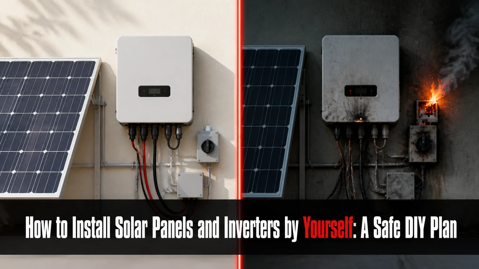
You can install solar panels and an inverter yourself by designing the system, obtaining permits, mounting the array, routing listed electrical equipment, passing inspection, and receiving utility permission to operate. A small ground-mounted or permitted roof-mounted system is the most manageable DIY path, but service-panel connections, grid interconnection, and energized testing should be reviewed or completed by qualified electricians.
Key Facts at a Glance
A grid-tied inverter must shut down during a utility outage unless the system includes approved islanding and backup equipment.
Solar panels produce DC electricity, while ordinary household branch circuits use AC electricity.
Array size depends on annual consumption, local solar resource, orientation, shading, temperature, and system losses.
A solar installation is not complete when the panels are mounted; permits, inspection, utility approval, and written permission to operate are separate requirements.
Microinverters reduce string-voltage design work, but they do not eliminate roof, AC, grounding, code, or utility hazards.
Never disconnect or probe energized PV conductors simply because the utility breaker is off. Sunlight can keep the array electrically live.
Before You Start: Is DIY Solar Appropriate?
DIY solar installation is reasonable for a homeowner who can plan accurately, work safely at height, follow manufacturer instructions, document every circuit, and coordinate the authority having jurisdiction, or AHJ. The safest division of labor is often homeowner-led design and racking with an electrician handling the service connection, inspections, and commissioning.
Roof work creates a separate hazard from electrical work. The U.S. Occupational Safety and Health Administration requires employers to provide fall-protection training for workers exposed to fall hazards, and its construction standard states that employers must provide “a training program for each employee who might be exposed to fall hazards.” A homeowner should use an appropriate guardrail, scaffold, or fall-arrest system designed for the roof rather than relying on a ladder.
DIY solar is a poor choice when the roof needs replacement, rafters are inaccessible or damaged, the service panel is undersized, asbestos or fragile roofing is present, the property has complex fire setbacks, or the system includes a large battery bank inside living space. A ground array can remove roof-leak and fall-access problems, although excavation, wind loading, frost depth, and permitting still apply.
DIY readiness checklist
| Requirement | Typical threshold or condition | Why it matters |
|---|---|---|
| Roof age | Fewer than 10 years remaining | Avoid removing a new array for reroofing |
| Array access | Stable work platform and fall protection | Reduces fall and dropped-object exposure |
| Service panel | Listed capacity and available connection method | Determines breaker or supply-side options |
| Design documents | Site plan, equipment schedule, one-line diagram | Supports permitting and inspection |
| Utility status | Written interconnection approval | Prevents unauthorized export |
| Electrical skill | Ability to read listings, torque values, and diagrams | Prevents polarity and connection errors |
Expert insight: The most expensive DIY mistake is often not a failed inverter. It is installing a structurally sound array that the AHJ or utility cannot approve because the design omitted setbacks, rapid shutdown, equipment listings, labeling, or an acceptable interconnection method.
How Does a Solar Panel and Inverter System Work?
A residential photovoltaic system follows this sequence: sunlight creates DC electricity in the modules, an inverter converts DC to synchronized AC, protective equipment routes AC to the home distribution system, and surplus generation may flow through a bidirectional meter to the utility. The inverter also monitors voltage, frequency, faults, and anti-islanding conditions.
A string inverter receives DC from one or more series-connected strings. A microinverter converts each module’s output near the panel, so the roof circuit becomes AC after each module. A hybrid inverter adds battery charging, discharge control, backup loads, and grid-management functions.
Net metering is not universal. Some utilities credit exports at retail rates, others use avoided-cost rates, monthly net billing, or time-based compensation. The meter may not literally “spin backward,” because many modern meters record import and export registers electronically. Confirm the tariff before sizing for maximum annual production.
Which Inverter Architecture Fits Your Installation?
For a simple roof with little shade, a string inverter usually provides the lowest equipment cost and centralized service. Microinverters are often easier to design around multiple roof orientations or partial shade, while a hybrid inverter is appropriate only when battery storage and backup-load design justify the additional controls and installation complexity.
| Attribute | String inverter | Microinverters | Hybrid inverter |
|---|---|---|---|
| Conversion location | Wall-mounted central unit | One unit per module | Central unit with battery interface |
| Typical PV input | 300-600 V DC strings | Module-level DC input | Model-dependent high-voltage or low-voltage DC |
| Roof output | DC until the inverter | AC trunk circuit | DC or AC, depending on architecture |
| Shade response | Reduced by weakest string conditions | Module-level optimization | Depends on MPPT and optimizer design |
| Typical inverter warranty | 10-15 years | 15-25 years, model dependent | 10-15 years |
| Battery integration | Separate battery equipment often needed | AC-coupled battery often added | Native battery control on compatible models |
| Main limitation | High-voltage DC and string design | More roof electronics and connectors | Highest design and commissioning complexity |
Microinverters do not automatically make a system safe for beginners. Roof-level AC circuits can still reach hazardous voltage, and every connector, trunk cable, grounding path, and rapid-shutdown component must be listed for the environment. String inverters also are not inherently unsuitable, but their maximum voltage, minimum operating voltage, cold-weather open-circuit voltage, and MPPT windows require exact calculations.
What equipment is required?
A typical grid-tied array includes listed PV modules, racking, attachment hardware, flashing, module-level or string inverters, rapid-shutdown equipment where required, DC or AC disconnects, overcurrent protection, grounding and bonding hardware, conduit, PV-rated conductors, labels, monitoring equipment, and a utility-approved interconnection method.
Off-grid systems additionally require a charge controller or compatible inverter charger, batteries, battery overcurrent protection, a properly designed distribution panel, and a generator or other backup source when energy availability is uncertain. A hybrid system needs a backed-up-loads panel or approved whole-home transfer arrangement. Never assume a battery inverter can energize an existing house panel without transfer protection.
How Do You Size the Solar Array and Inverter?
Size the array from measured electricity use and location-specific production, not from an average-household shortcut. Use the annual or monthly consumption from utility bills, a reputable solar-resource model, the proposed azimuth and tilt, shading losses, temperature effects, inverter efficiency, and allowable export under the utility tariff.
A useful preliminary equation is:
[ \text{Array size in kW DC} = \frac{\text{Daily load in kWh}} {\text{Peak-sun-hours} \times \text{performance ratio}} ]
For example, 30 kWh per day, 4.5 peak-sun-hours, and a 0.80 performance ratio produce:
[ 30 \div (4.5 \times 0.80)=8.33\text{ kW DC} ]
Twenty-one 400-watt modules provide 8.4 kW DC. At approximately 20 square feet per module, the modules alone require about 420 square feet, before fire pathways, roof edges, access clearances, vents, and irregular layout gaps.
| Input | Example value | Design consequence |
|---|---|---|
| Daily consumption | 30 kWh | Annual load equals about 10,950 kWh |
| Peak sun hours | 4.5 hours/day | Production varies by location and season |
| Performance ratio | 0.80 | Accounts for thermal, wiring, soiling, and conversion losses |
| Module rating | 400 W | 21 modules produce 8.4 kW DC |
| Module area | 20 sq ft | Bare module area is about 420 sq ft |
| Inverter rating | 7.6-8.0 kW AC | DC-to-AC ratio is approximately 1.05-1.11 |
The inverter is not sized by panel wattage alone. Check the inverter’s maximum DC voltage against the coldest expected module open-circuit voltage, verify string voltage remains inside the MPPT range in hot conditions, and keep current below each input’s limit. Use the module datasheet temperature coefficient and the inverter installation manual, not a generic online calculator.
Expert insight: A 400-watt module is a power rating under laboratory conditions, not a promise of 400 watts throughout the day. A south-facing array with winter shading can produce less annual energy than a slightly larger east-west array with fewer shade hours.
Should You Choose a Roof Mount or Ground Mount?
Choose a ground mount when land, drainage, setbacks, and local approval are available and roof access is difficult. Choose a roof mount when the roof is structurally sound, unshaded, expected to last through the system’s service life, and large enough to preserve required pathways.
| Factor | Roof mount | Fixed ground mount | Pole or tracker mount |
|---|---|---|---|
| Typical installation surface | Asphalt, metal, tile, membrane roof | Soil, gravel, concrete footings | Engineered pole foundation |
| Roof-leak exposure | Present | None | None |
| Excavation | Usually none | Posts, trench, or footings | Foundation and trenching |
| Maintenance access | Restricted | Usually straightforward | Straightforward but mechanical |
| Common constraint | Rafters and fire setbacks | Property setbacks and frost | Wind loads and moving parts |
| Best DIY advantage | Lower civil-work cost | Safer access and easy expansion | Higher site flexibility |
| Typical added cost | $0 baseline | $1,000-$4,000 civil and racking work | $3,000 or more for tracker hardware |
Do not mount over a roof that has brittle tiles, uncertain attachment points, active leaks, or fewer than the expected remaining service years. Obtain a structural review when the array is large, the roof has unusual framing, the site has high snow or wind loads, or the racking manufacturer requires engineering.
Step 1: Design the Layout and Obtain Approval
Create a scaled site plan showing module dimensions, roof edges, ridges, hips, valleys, vents, skylights, electrical equipment, conduit routes, and structural attachment points. Create a one-line electrical diagram that identifies module groups, inverter inputs, disconnects, overcurrent protection, grounding and bonding, conductor types, breaker ratings, and the connection point.
Submit the documents required by the AHJ before buying equipment. Requirements commonly include building, electrical, structural, fire-access, and utility-interconnection documents, but the exact package depends on the jurisdiction. The National Electrical Code, local amendments, utility rules, and equipment listing requirements control the final design.
You will know the design phase is complete when the permit office accepts the application, the utility accepts the interconnection request or gives conditional approval, and every major component appears on the approved equipment schedule.
Common mistake: Designing around a preferred inverter before checking the utility’s export limit, service capacity, or approved equipment list.
Step 2: Stage Tools, Materials, and Safety Controls
Stage the module pallets, rails, flashing, attachments, conduit, conductors, labels, torque tools, roof access equipment, fall protection, lifting equipment, and weatherproof storage before beginning. Use the racking manufacturer’s attachment spacing, rail spans, clamp zones, fastener type, and torque values because those values vary by product and wind or snow rating.
| Item | Typical quantity for 8.4 kW example | Verification |
|---|---|---|
| 400 W modules | 21 | Datasheet dimensions and electrical ratings |
| Microinverters | 21, or manufacturer-approved multi-module units | Maximum module power and trunk capacity |
| Aluminum rails | 8-12 rails, layout dependent | Span tables and roof geometry |
| Roof attachments | 30-45, layout dependent | Rafter location and engineering |
| PV conduit | 50-150 feet | Route, temperature, fill, and support |
| PV wire | 200-500 feet | Ampacity, insulation, sunlight rating |
| Torque wrench | 1 calibrated tool | Fastener and clamp specifications |
| Fall-protection system | 1 complete system per worker | Roof and anchor compatibility |
Work only in dry conditions with low wind, secure loose materials, keep people below clear of the drop zone, and never carry a module up a ladder while both hands are occupied. Panel glass and aluminum frames can be damaged by point loading or twisting.
Step 3: Install Flashing, Attachments, and Rails
Mark every attachment from the approved layout, then confirm the structural member before drilling. For a shingle roof, the flashing must extend under the correct shingle course and over the attachment penetration according to the racking instructions; sealant alone is not a substitute for properly integrated flashing.
Drill pilot holes of the specified diameter and depth, apply only the approved sealant where required, and install the lag or structural screw perpendicular to the framing. Do not guess the rafter center from a single measurement. Verify from roof framing information, repeated measurements, and the attachment position before tightening.
Attach rails, maintain required end and splice clearances, and torque every fastener with a calibrated wrench. Keep rail ends within the manufacturer’s cantilever limit and bond rail sections with listed bonding hardware where the system requires it.
You will know the mechanical stage is successful when each attachment reaches solid framing, flashing lies flat, rails meet span and alignment requirements, and the installation record contains torque and photo documentation.
Common mistake: Driving a lag near the rafter edge. The connection may feel tight while providing inadequate withdrawal strength and creating a leak path.
Step 4: Install Inverters and Manage Conductors
Install microinverters in the permitted orientation and temperature range, leaving service access and avoiding locations where water can collect. Connect only compatible module connectors, keep unused connectors capped with listed caps, and secure conductors with approved clips so cables do not rest on roofing, sharp edges, or standing water.
For a string inverter, mount the unit on a noncombustible or approved surface with the clearances specified by its manual. Design strings to satisfy maximum voltage in the coldest condition and minimum MPPT voltage in the hottest operating condition. Route DC conductors in a suitable raceway where required, and separate circuits as the code and equipment instructions specify.
Rapid shutdown is a system function, not a label. The required equipment depends on the jurisdiction, array boundary, inverter architecture, and applicable code edition. Confirm the shutdown initiation method and module-level voltage behavior before inspection.
Common mistake: Treating connector compatibility as universal. Similar-looking PV connectors from different manufacturers may not be approved for mating, even when they physically fit.
Step 5: Mount Modules and Complete Bonding
Place each module inside the permitted clamp zones shown on the module datasheet. Install end clamps and mid-clamps without pinching cables, then torque them to the racking manufacturer’s specified value. A common range is approximately 8-15 foot-pounds, but the manual controls.
Bond exposed conductive metal using listed clips, lugs, jumpers, and grounding conductors. Do not assume a bare copper conductor of a particular size, such as number 6 AWG, is universally correct. Conductor sizing depends on the overcurrent device, fault-current calculations, installation method, temperature, corrosion environment, and local code.
Connect module leads with correct polarity and bend radius. Do not unplug connectors under load. Covering modules reduces output but does not make the circuit reliably de-energized, so use the manufacturer’s shutdown procedure and appropriate test equipment.
You will know the array stage is successful when modules are aligned, clamps are inside approved zones, cables are supported, connectors are fully seated, bonding hardware is installed, and the as-built layout matches the permit drawings.
Step 6: Complete AC Connection and Commissioning
Route AC conductors or conduit from the inverter equipment to the approved connection point, install required disconnects and labels, and verify conductor ampacity, voltage drop, equipment grounding, and overcurrent protection. A main-panel breaker connection must satisfy the adopted electrical code and the panel manufacturer’s listing.
The often-cited 120% busbar rule is not a universal permission to place a solar breaker anywhere. The result depends on busbar rating, main-breaker rating, panel labeling, breaker position, backfeed rating, utility requirements, and alternative connection methods such as a supply-side connection. A licensed electrician should evaluate the service equipment before any panel work.
Do not test live terminals casually with a handheld multimeter. Commissioning can involve lethal AC and DC energy, arc-flash exposure, and utility hazards. Have the qualified person verify polarity, insulation condition, grounding continuity, disconnect operation, rapid shutdown, inverter settings, and monitoring communication.
The final sequence is inspection, correction of any deficiencies, utility meter or interconnection work, written permission to operate, and controlled startup. A grid-tied inverter should remain off-grid disabled until PTO is issued.
How Much Does DIY Solar Cost and How Long Does It Take?
A typical homeowner-led 8 kW grid-tied system costs approximately $10,000-$18,000 before incentives when equipment, permits, design review, rentals, and contingency are included. A straightforward ground-mount can cost more than a roof array because posts, trenching, foundations, and longer wire runs add civil and electrical work.
| Cost component | Typical range for 8 kW | Main price driver |
|---|---|---|
| PV modules | $2,000-$4,000 | Wattage, brand, shipping, quantity |
| Inverters | $2,000-$5,000 | String, microinverter, hybrid, warranty |
| Racking and flashing | $1,500-$3,500 | Roof type, attachment count, engineering |
| Wire, conduit, protection | $1,000-$2,500 | Run length, service connection, trenching |
| Permits and design | $500-$2,000 | AHJ and structural requirements |
| Equipment rental and contingency | $1,000-$3,000 | Lift, scaffold, replacement hardware |
Expect 40-80 homeowner labor hours for a simple system, spread across two to five weekends, excluding permit waiting and utility scheduling. A roof with difficult access, tile replacement, multiple orientations, or a battery can extend the project substantially.
Federal, state, and local incentives change by location and tax situation. The U.S. Department of Energy advises checking current federal and state programs rather than relying on an old installer quote.
What Are the Most Common DIY Failures?
The most common failures are incorrect structural attachments, incompatible connectors, undersized conductors, unapproved equipment, missing rapid-shutdown components, inadequate labeling, and an interconnection design that the utility rejects. Each failure has a different remedy, so do not troubleshoot by repeatedly resetting the inverter.
| Symptom | Safe first check | Likely cause | Escalation point |
|---|---|---|---|
| Inverter says grid missing | Confirm approved disconnect status | Open breaker, wiring fault, utility outage | Electrician verifies AC voltage |
| Ground or insulation fault | Shut down using documented procedure | Pinched cable, damaged insulation, moisture | Qualified PV technician tests insulation |
| Low production | Compare monitoring by module or string | Shade, soiling, failed optimizer, snow | Technician performs electrical diagnosis |
| Rapid shutdown fault | Check initiator and communication status | Missing device, wiring, or configuration error | Installer checks system topology |
| Battery will not charge | Review state-of-charge and temperature limits | Incorrect mode, temperature lockout, wiring | Battery-certified technician |
| Utility rejects application | Compare as-built system with approved plan | Unlisted equipment or missing calculations | Designer revises and resubmits |
Never measure string open-circuit voltage or insulation resistance unless trained and equipped for the voltage category. When a fault remains after visual inspection and documented shutdown, stop work and call a qualified solar electrician.
Which Alternatives Make More Sense?
A professional turnkey installation makes more sense when the roof is steep, the service needs upgrading, the project includes batteries, the local permit process is complex, or workmanship warranties and a single responsible contractor have high value. A professional-assisted DIY package can reduce labor cost while supplying stamped plans, equipment selection, and inspection support.
A portable power station is a different product. It can power selected appliances through approved outlets or transfer equipment, but it does not replace a permitted rooftop PV system and usually cannot run a whole home continuously.
Community solar may be the better alternative for renters, shaded properties, condominium owners, or households unable to modify a roof. Community-solar credits and contract terms vary by utility and state.
Which situation favors each path?
| Situation | Preferred path | Reason |
|---|---|---|
| Unshaded roof, simple service, no battery | DIY or assisted DIY | Lowest design complexity |
| Frequent outages and medical loads | Professional hybrid system | Backup transfer and battery sizing require careful design |
| Remote cabin with no utility | Engineered off-grid system | Battery autonomy and generator integration dominate |
| Renter or shaded apartment | Community solar | No roof ownership or structural work |
| Roof replacement due within 5 years | Delay or reroof first | Avoid removal and reinstallation cost |
| Complex tile roof and high wind | Professional installation | Waterproofing and structural risk are high |
Is DIY Solar Worth It?
DIY solar can be financially worthwhile when the system is simple, the homeowner can perform mechanical work safely, and local rules permit owner participation. Savings come mainly from avoided labor and project-management charges, while design review, permits, electrical work, lifting equipment, and warranty limitations reduce the headline difference.
DIY solar is not a good bargain if one failed roof penetration causes interior damage, if an unapproved system loses net-billing eligibility, or if the homeowner cannot obtain insurance or future service. The best practical model is often hybrid: hire a qualified designer or electrician for the electrical and structural boundary, then perform permitted staging, racking, module mounting, and documentation yourself.
Practitioner rule: Budget a 10-15% contingency for replacement connectors, shipping damage, extra conduit, permit revisions, and overlooked roof obstructions. A zero-contingency bill of materials is usually an incomplete bill of materials.
FAQ
Can I install solar panels without connecting them to the grid?
Yes, a permitted off-grid or self-consumption system can operate without utility interconnection, but it still needs correctly sized batteries, charge control, overcurrent protection, grounding, disconnects, and safe transfer arrangements. A grid-tied inverter cannot normally power a disconnected house during an outage because anti-islanding protection disables it.
Do solar panels work during a power outage?
Standard grid-tied solar panels do not power household circuits during a utility outage. An approved hybrid inverter, battery, transfer function, and backed-up-loads panel are required to create an energized local microgrid while keeping utility conductors isolated.
Can I install solar panels on an asphalt-shingle roof?
Yes, asphalt-shingle roofs commonly accept solar attachments when the roof is sound and the racking uses compatible flashing and structural fasteners. The installer must locate rafters accurately, preserve shingle drainage, respect edge and fire clearances, and avoid covering a roof that will soon need replacement.
How many batteries do I need for an off-grid solar system?
Battery quantity depends on daily critical load, desired autonomy, usable depth of discharge, inverter efficiency, temperature, and charging conditions. For example, 15 kWh of usable storage with an 80% allowable depth of discharge requires at least 18.75 kWh of nominal battery capacity before additional cold-weather and conversion allowances.
Does adding more panels always increase solar savings?
No. Additional panels increase generation only when roof space, inverter input capacity, utility export rules, and tariff compensation support the extra output. Under low export rates, shifting energy use into daylight or adding controlled storage may produce greater financial value than maximizing array wattage.
What should I do if the inverter shows a fault after installation?
Record the exact code, review the manufacturer’s shutdown and restart sequence, inspect only accessible de-energized components, and verify whether the utility has power. Do not open energized equipment or test PV strings without suitable training. Persistent ground, insulation, arc, or grid-voltage faults require a qualified technician.
The Bottom Line
To install solar panels and inverters by yourself, begin with consumption data, a site and structural assessment, an equipment-compatible electrical design, and written AHJ and utility requirements. Install the mechanical array only when the roof or ground structure, fall protection, flashing, racking, conductors, bonding, and rapid-shutdown design are documented. Treat the service-panel connection, live testing, inspection corrections, and permission to operate as professional electrical work unless your jurisdiction explicitly permits and you are qualified to perform it.
DIY solar succeeds through accurate design and compliant commissioning, not through purchasing panels cheaply. For many homeowners, a permitted assisted-DIY project delivers the best balance of savings, safety, approval, and long-term serviceability.