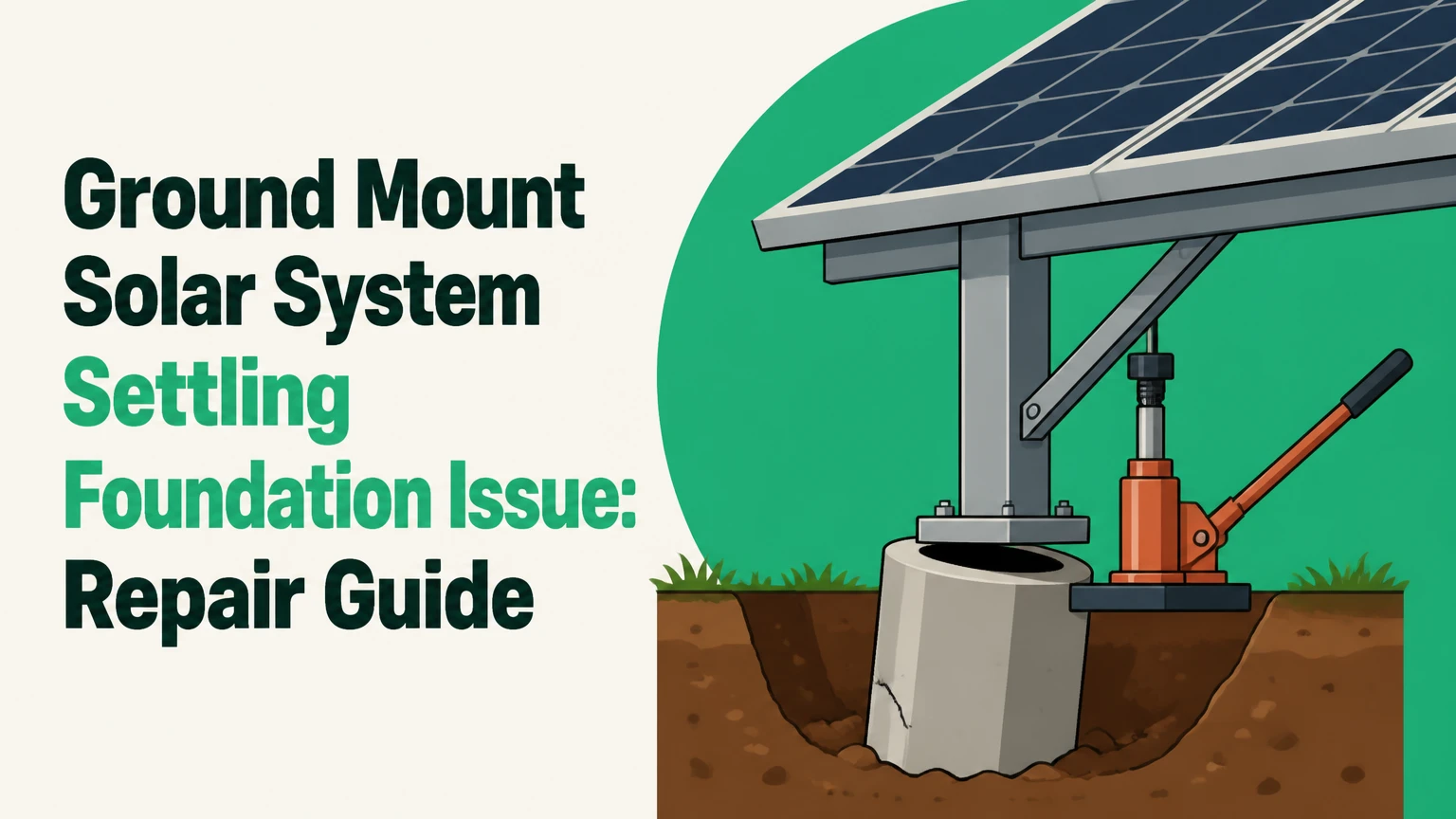
A ground mount solar system settling foundation issue occurs when one or more supports move vertically or rotate relative to the rest of the array, producing differential settlement, frost heave, erosion, or structural tilt. The correct response is to stop loading the distorted structure, document movement, obtain structural and geotechnical evaluation, and transfer loads to foundations designed for the actual soil conditions.
Key Facts at a Glance
- Differential settlement means adjacent solar supports move by different amounts, not merely that the entire array sits low.
- A bent rail, cracked module, loose clamp, or changed tilt angle can indicate foundation movement, but electrical output alone cannot diagnose settlement.
- Foundation depth, pile spacing, diameter, embedment, and capacity are project-specific values determined by soil, wind, snow, array geometry, and local code.
- Hydraulic lifting can realign a rack, but lifting without temporary shoring can overload rails, bolts, modules, and conductors.
- Helical-pile torque is installation evidence, not a universal load rating; the engineer must correlate torque with the installed pile and soil profile.
- Typical residential remediation costs range from about $4,500 to $15,000 or more, excluding extensive module replacement, access work, and major civil reconstruction.
What Is a Ground Mount Solar System Settling Foundation Issue?
A ground-mounted solar foundation issue is a loss of designed position or capacity in the supports beneath a photovoltaic array. The movement may be downward settlement, upward frost heave, sideways sliding, rotation, or erosion beneath a ballast block.
Differential settlement is the most damaging form because the racking connects supports into one structural system. If one post sinks 25 millimeters while the next post remains fixed, the beam between them bends and twists instead of moving as a unit. That distortion can transfer force into module frames, clamps, splice joints, pile connections, and electrical cable management.
A level-looking row can still have a serious foundation problem. Survey the top of the rack, the post heads, and the ground around each support separately. A tracker also requires inspection of drive torque, gear alignment, stow position, and actuator travel.
Settlement, Frost Heave, or Erosion?
Settlement moves a support downward because the soil compresses, shears, or loses confinement. Frost heave moves a support upward when freezing water expands or frost adhesion lifts the foundation, often followed by uneven movement during thaw. Erosion removes supporting soil, usually around ballasted pads, sloped sites, drainage outlets, or poorly protected post excavations.
| Movement mechanism | Typical field evidence | Main season or trigger | Primary confirmation |
|---|---|---|---|
| Consolidation settlement | Post head lower than adjacent posts; fresh rail sag | Months to years after loading | Level survey and soil investigation |
| Frost heave | Post higher after winter; cracking or seasonal tilt | Freeze and thaw cycles | Seasonal surveys and frost-depth review |
| Surface erosion | Exposed ballast edge; rills; voids beside footing | Heavy rainfall or snowmelt | Drainage inspection and elevation survey |
| Expansive clay movement | Repeated tilt during wet and dry cycles | Moisture variation | Soil classification and moisture profile |
| Construction defect | Movement concentrated at poorly installed supports | Early service period | Installation records and foundation inspection |
The distinction controls the repair. Underpinning a support that is actually being lifted by frost or expansive clay may increase restraint while leaving the moisture problem unresolved.
Why Does a Solar Foundation Settle?
A solar foundation settles when the soil and foundation system cannot maintain the required compression, uplift, and lateral resistance under actual site conditions. The most common causes are uncompacted fill, soft saturated layers, inadequate embedment, poor drainage, construction disturbance, and incorrect assumptions about soil strength.
Solar arrays impose more than panel weight. Wind can create uplift on the modules and overturning at the supports, while snow adds downward load. Unequal support stiffness causes one foundation to attract more force than neighboring foundations, increasing movement after the first displacement.
What Soil and Site Conditions Increase Risk?
Uncompacted fill is especially risky because its density and material can change over short distances. Saturated silt or loose sand may lose effective strength, while expansive clay changes volume with water content. Rock can prevent driven piles from reaching the intended position and can force shallow or eccentric concrete placement.
Water is often the hidden driver. Rooflike module surfaces shed rainfall toward the ground, and concentrated runoff can soften soil or scour ballast bedding. A post that appears structurally sound may still have reduced capacity if water has created a void beside its footing.
The 2024 International Building Code and local amendments govern structural design in many United States jurisdictions, but neither supplies one universal solar-pile depth. The design must account for local wind and snow data, frost conditions, soil parameters, and the racking manufacturer’s connection requirements.
How Do You Diagnose Movement Safely?
Diagnose a settling array with a controlled survey, visual inspection, connection review, and soil assessment before attempting to lift or tighten anything. A single photograph or generation report cannot establish foundation movement or structural capacity.
First, isolate immediate hazards. Keep people away from visibly collapsing racks, exposed conductors, leaning modules, unstable ballast, and areas where excavation could undermine a support. A qualified electrical professional should determine whether the array can remain energized, because photovoltaic conductors may remain live in daylight even after an inverter is turned off.
Record the original design if available: foundation coordinates, pile type, embedment, torque logs, concrete details, module layout, design tilt, and as-built elevations. Then establish stable survey benchmarks outside the array and measure post heads, beam elevations, row alignment, and module-plane angle.
| Diagnostic check | Typical field method | Useful trigger for escalation | Result |
|---|---|---|---|
| Post elevation | Optical level, laser level, or robotic total station | Adjacent supports differ by 10-15 mm | Settlement map |
| Rack alignment | String line, laser, or total station | Rail deviation exceeds design tolerance | Distortion record |
| Module condition | Visual inspection and electroluminescence testing | Glass cracks, frame bowing, hot spots | Damage assessment |
| Bolt movement | Paint witness marks and torque audit | Witness line breaks or torque falls | Connection investigation |
| Soil condition | Hand probing, test pits, boring, or CPT | Soft layer, void, seepage, or fill | Geotechnical model |
| Electrical condition | Insulation resistance and continuity testing | Cable tension, insulation damage, or ground fault | Electrical release decision |
There is no universal “acceptable” settlement value for every array. A 10-millimeter differential over a short bay can be more damaging than a larger uniform movement across the whole table, so the engineer should assess distortion, connection rotation, and remaining capacity rather than relying on one number.
Can the Array Be Jacked Back Into Position?
A settled solar array can often be lifted and realigned, but jacking is a temporary stabilization operation, not the foundation repair itself. Hydraulic jacks, spreader plates, and engineered cribbing must support the rack at locations that will not crush aluminum members or load module frames.
Before lifting, the engineer should define the lift points, maximum incremental movement, temporary bracing, sequence, and stop conditions. Lifting in small increments, commonly 5-10 millimeters per stage, reduces sudden load redistribution; the actual limit depends on rack geometry and observed damage.
Never use a jack directly against a module, thin rail, cable tray, or unverified beam. Do not loosen every module clamp at once, because uncontrolled movement can allow modules to slide or fall. The array may need partial module removal to expose posts and prevent frame damage.
You know the lifting stage is controlled when survey readings match the approved target, temporary supports remain plumb, no rail buckling occurs, and connection movement stays within the engineer’s specified limit. Stop immediately for cracking, popping, cable tension, sudden jack-load loss, or movement in an adjacent support.
Which Foundation Type Fits the Site?
No foundation type is universally best. Driven piles usually suit repetitive arrays with predictable soils and equipment access, helical piles suit sites requiring torque verification or limited vibration, concrete piers suit engineered shallow excavation where frost and drainage are controlled, and ballast suits sites where penetration is prohibited.
| Foundation type | Typical installation range | Main capacity evidence | Common limitation |
|---|---|---|---|
| Driven steel pile | 2.5-5 m embedment, project-specific | Blow count, refusal, load testing, survey | Rock, vibration, refusal, access |
| Helical pile or ground screw | 1.5-5 m embedment, project-specific | Installation torque and load test | Very dense rock, corrosion exposure |
| Cast-in-place concrete pier | 0.6-2.5 m diameter or smaller engineered shaft | Concrete strength, reinforcement, soil bearing | Excavation, curing, groundwater |
| Precast ballast block | Surface-mounted, often 0.15-0.6 m thick | Block weight, friction, subgrade bearing | Washout, large footprint, slope |
| Micropile or drilled shaft | 5-20 m or more where engineered | Grout records, bond, load testing | Specialized equipment and high cost |
The dimensions above are typical project ranges, not installation instructions. A supplier’s advertised vertical rating, such as 15,000 pounds, cannot be transferred to a different soil, shaft length, helix configuration, corrosion condition, or lateral load case without engineering verification.
Are Helical Piles Better Than Concrete Piers?
Helical piles are often better for wet sites, restricted access, and repairs requiring immediate load transfer, while concrete piers may be more economical for small arrays with suitable excavation conditions. Helical installation torque must be logged and interpreted against the manufacturer’s tested soil correlations or project load tests.
Concrete is not automatically stronger. A shallow concrete pier in loose fill can perform worse than a properly installed helical pile, and a helical pile stopped at low torque can perform worse than a correctly reinforced pier. The soil profile and load path decide the outcome.
Driven piles can be the lowest-cost foundation on large, clear sites, but refusal and vibration risks need early investigation. Ballast avoids penetration but transfers demand to the subgrade and requires a designed drainage and bedding system.
How Is a Settled Foundation Repaired?
A settled foundation is repaired by identifying the movement mechanism, temporarily supporting the array, correcting or bypassing the failed soil, transferring loads to verified supports, and documenting the final alignment. Cosmetic leveling without load transfer leaves the original failure in place.
Step 1: Secure the Array and Document Damage
Shut down or isolate equipment according to the electrical design, restrict access, photograph every affected support, and mark rail elevations. Record cracked glass, frame deformation, loose clamps, cable tension, ground-fault alarms, and water pathways before disturbing the system.
Step 2: Complete Engineering and Soil Investigation
Use a structural engineer familiar with photovoltaic racking and a geotechnical professional when soil capacity, groundwater, fill, or recurrent movement is uncertain. The investigation may include test pits, borings, cone penetration testing, laboratory classification, groundwater observation, and foundation exposure.
Step 3: Install Temporary Shoring
Place engineered cribbing or shoring beneath approved rack points before removing load from a failed support. Temporary works must account for wind, construction loads, partial module removal, and the possibility that the array behaves differently after a connection is released.
Step 4: Lift and Realign in Controlled Increments
Jack the affected bay only as far as necessary to reach the approved geometry. Survey after each increment and inspect for rail buckling, fastener slip, module-frame stress, and conductor strain.
Step 5: Underpin or Replace the Support
Possible solutions include adjacent helical piles with engineered brackets, deeper replacement piers, enlarged reinforced concrete foundations, micropiles, or complete footing replacement. The repair must transfer load through a designed steel bracket or connection, not through loose soil packed around the old post.
Step 6: Restore Drainage and Soil Support
Grade water away from posts and ballast, repair rills and voids, install erosion protection where designed, and avoid placing uncontrolled soil against galvanized steel. For expansive soils, drainage correction may be as important as the new foundation.
Step 7: Reassemble, Test, and Monitor
Retorque structural fasteners to the racking manufacturer’s values, inspect module clamps, verify bonding and grounding, test insulation resistance where appropriate, and compare final elevations with the repair drawings. Schedule follow-up surveys after a major rainfall or freeze-thaw cycle.
What Repair Errors Cause Repeat Settlement?
The most expensive repair error is correcting the visible tilt while leaving the water, fill, or weak soil that caused movement. A successful underpinning project must connect the original structure to verified capacity and address the environmental condition that reduced capacity.
- Jacking before shoring: Sudden load transfer can bend rails or crack glass. Install temporary supports first.
- Using depth as a substitute for capacity: A deeper pile with inadequate torque or unsuitable soil is not automatically reliable. Verify installation records or perform load testing.
- Pouring concrete into unstable or wet excavation: Sidewall collapse and contaminated concrete reduce shaft quality. Use an engineered excavation and placement method.
- Ignoring differential movement: Raising one post to match a neighboring post can create a new twist. Survey the entire connected bay.
- Tightening distorted clamps: More torque cannot remove structural misalignment and may damage module frames. Correct geometry before final torque.
- Leaving drainage unchanged: Repaired supports can settle again when runoff continues to saturate or scour the same location.
A practitioner rule is to treat every displaced support as part of a connected load path. Inspect at least the adjacent supports, the beam or rail span, and the electrical slack on both sides.
How Much Does Solar Foundation Repair Cost?
Typical residential or light-commercial remediation costs range from $4,500 to $15,000, while extensive commercial repairs can exceed $25,000 when many piles, modules, access routes, or civil works require replacement. Actual cost depends more on access, array size, damage, and foundation count than on the price of a single pile.
| Work item | Typical cost range | Typical duration | Main cost variable |
|---|---|---|---|
| Site inspection and survey | $500-$2,000 | 0.5-2 days | Array size and survey control |
| Geotechnical testing | $1,000-$5,000 | 1-4 weeks including report | Borings, CPT, laboratory work |
| Structural repair design | $1,500-$7,500 | 1-4 weeks | Damage and permit requirements |
| Hydraulic lift and shoring | $2,000-$8,000 | 1-3 days | Module removal and access |
| Helical-pile underpinning | $3,000-$12,000 | 1-3 days | Pile count and bracket design |
| Concrete footing replacement | $4,000-$15,000 | 3-10 days | Excavation, rebar, curing, groundwater |
| Module or electrical replacement | $300-$1,500 per module | 1-3 days | Module model and cable damage |
These are typical planning ranges, not bids. Concrete work can require additional curing time before full design loading, whereas a helical pile may accept load immediately if the engineer approves the installation and connection.
Permitting may take 2-6 weeks depending on the authority having jurisdiction, structural review, utility requirements, and whether the repair changes the approved array layout. Physical work often takes 2-5 days for a small system after engineering and materials are complete.
How Can Future Settlement Be Prevented?
Prevent settlement by matching the foundation system to verified soil conditions, controlling water, recording installation evidence, and surveying the completed array. Prevention begins before procurement because a racking system cannot compensate for an unknown or poorly prepared subgrade.
| Prevention control | Minimum record or action | Verification timing | Failure avoided |
|---|---|---|---|
| Soil investigation | Boring, CPT, or documented competent native soil | Design stage | Uncompacted fill and soft-layer assumptions |
| Foundation installation | Depth, alignment, torque or concrete placement log | Every support | Unverified capacity |
| Survey control | Post coordinates and elevations | Before and after installation | Hidden initial misalignment |
| Water management | Grades, swales, outlets, and erosion details | Before energization and after storms | Saturation and washout |
| Connection control | Manufacturer torque values and witness marks | Installation and maintenance | Clamp or bolt slip |
| Seasonal inspection | Photos, levels, cracks, vegetation, and drainage | Spring and autumn | Delayed movement detection |
The U.S. Department of Energy’s Solar Best Practices guide emphasizes site-specific design, inspection, and operations procedures rather than a universal foundation recipe. That principle matters because frost depth, wind exposure, snow load, soil density, and groundwater can vary substantially between neighboring parcels.
Ballasted arrays need special attention to subgrade preparation. A concrete block on compacted aggregate with positive drainage behaves differently from the same block placed on topsoil beside a concentrated downspout.
Which Situations Need a Different Repair Strategy?
Expansive clay requires moisture management and movement analysis, not merely deeper supports. Wet sites may favor helical or drilled systems after groundwater and corrosion conditions are reviewed. Rocky sites may require drilled shafts, micropiles, or redesigned locations after refusal mapping.
Landfills and brownfields introduce environmental and settlement constraints. Penetrating a cap or placing foundations in uncontrolled waste may be prohibited, and a ballasted solution may still fail if the cover settles unevenly. The environmental engineer, geotechnical engineer, and permitting authority should approve the foundation concept before construction.
Sloped sites require both foundation capacity and global stability review. A support can remain plumb while the soil mass beneath the array moves downslope. Surface drainage, retaining structures, shallow slip planes, and access-road runoff may therefore matter more than individual post depth.
Trackers require additional checks. A small foundation rotation can cause torque-tube misalignment, actuator binding, stow failure, and uneven backtracking. The system should not be forced through a jammed position.
When Should a Homeowner Call a Professional?
A homeowner should stop work and call a structural or solar-racking professional when a post has visibly shifted, a rail is bowed, glass is cracked, a tracker binds, electrical alarms appear, or soil has washed away around a support. Foundation excavation and jacking are not suitable trial-and-error repairs.
Homeowners can safely collect photographs, dates, weather history, inverter alerts, module serial numbers, and original installation documents from a safe distance. They should not loosen clamps, cut conductors, excavate beside a loaded post, or place a vehicle jack under the rack.
A commercial owner should preserve pile-driving records, torque logs, concrete tickets, survey files, geotechnical reports, and weather records. Those documents can determine whether the issue is a design error, installation defect, site change, storm event, or warranty matter.
Frequently Asked Questions
Can I add gravel around a sinking solar post?
Adding gravel around a sinking post rarely restores structural capacity because loose fill does not transfer the designed axial, uplift, and lateral loads to competent soil. Gravel can improve surface drainage when placed as part of an engineered grading plan, but a moving support usually needs underpinning, replacement, or a redesigned foundation.
Will insurance cover a settled ground-mounted solar array?
Insurance coverage depends on the policy, cause of loss, exclusions, and whether the array is residential, agricultural, or commercial. Sudden storm damage may receive different treatment from gradual settlement, defective construction, or excluded earth movement. Obtain an engineer’s report and notify the insurer before destructive repairs.
How often should a ground-mounted solar array be inspected?
Inspect a fixed array at least twice each year, typically after winter and before the severe-weather season, and inspect it after flooding, major rainfall, high wind, or vehicle impact. Check elevations, rail straightness, post plumb, ballast voids, drainage, clamps, conductors, and inverter alarms.
Can panel output prove that the foundation has settled?
Panel output cannot prove foundation settlement because shading, inverter faults, soiling, degradation, connector failure, and module mismatch can produce the same electrical symptom. Localized output loss combined with rail distortion or cracked glass increases suspicion, but a structural survey and electrical testing are still required.
Are concrete piers always deeper than the frost line?
Concrete piers should extend below the locally required frost depth when frost-susceptible soil and code conditions require it, but depth alone does not prevent heave. Drainage, reinforcement, shaft geometry, soil classification, uplift resistance, and isolation from frost-active soil may also control the design.
The Bottom Line
A ground mount solar system settling foundation issue is a structural and geotechnical problem, not a simple leveling defect. Confirm the movement mechanism, secure the array, survey the entire load path, and use engineered underpinning or replacement foundations that match the actual soil and water conditions. Do not accept a cosmetic lift without verified load transfer, drainage correction, connection inspection, and post-repair monitoring.