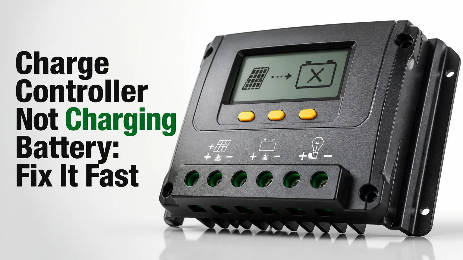
A charge controller not charging a battery from panels usually indicates low battery voltage, missing PV input, incorrect battery settings, excessive loads, or a controller fault. Test the battery at the controller terminals first, then test solar voltage, inspect fuses and connectors, verify chemistry settings, and reconnect the battery before the panels.
Key Facts at a Glance
- A solar charge controller normally needs a recognizable battery voltage before it can regulate panel energy.
- A 12 V lead-acid battery commonly shows 12.4-12.8 V at rest, while a LiFePO4 battery commonly shows 13.0-13.6 V.
- An MPPT controller generally needs PV voltage several volts above battery voltage before charging begins.
- Panel open-circuit voltage does not prove that a panel can deliver useful charging current under load.
- Connecting the battery before the PV array lets many controllers detect system voltage correctly.
- A LiFePO4 battery may show normal voltage while its battery-management system has opened the charge path.
What Does a Solar Charge Controller Do?
A solar charge controller regulates direct-current energy between photovoltaic panels and a battery bank. The controller measures battery voltage, limits charging current, and changes its output through bulk, absorption, and float or standby behavior so the battery receives a chemistry-appropriate charge.
A typical 12 V nominal panel may produce about 18-22 V at its maximum power point, while a 12 V battery may need approximately 14.0-14.7 V during lead-acid absorption. An MPPT controller converts the panel’s higher voltage into charging current. A PWM controller instead connects and disconnects the panel rapidly, so panel voltage must closely match battery voltage.
The charging path is:
Panel array → PV fuse or breaker → controller PV terminals → controller battery terminals → battery fuse or breaker → battery bank
A failure anywhere in that path can produce the same symptom: the display is on, but charging current remains zero. The first task is therefore to separate a battery-recognition fault from a solar-input fault.
How should normal charging behave?
Normal charging begins with bulk operation, where the controller supplies as much available current as the battery and system allow. During absorption, the controller holds a target voltage while current gradually falls. Float maintains a lead-acid battery at a lower voltage, while many lithium systems stop or enter standby rather than float continuously.
| Battery type | Typical bulk or absorption voltage, 12 V bank | Float behavior | Temperature compensation |
|---|---|---|---|
| Flooded lead-acid | 14.4-14.8 V | 13.2-13.6 V | Usually enabled |
| AGM lead-acid | 14.2-14.6 V | 13.2-13.6 V | Usually enabled |
| Gel lead-acid | 14.0-14.4 V | 13.5-13.8 V | Manufacturer-dependent |
| LiFePO4 | 14.0-14.6 V | Often disabled | Usually disabled |
| Lithium-ion NMC | 16.8 V for a 4-series pack | Battery-specific | BMS-controlled |
Exact values belong to the battery manufacturer. A controller set to flooded lead-acid can undercharge or improperly manage lithium batteries, and a lithium profile can overcharge an unsuitable lead-acid battery.
Why Is the Charge Controller Not Charging the Battery?
The most common causes are a battery below the controller’s startup threshold, zero or inadequate PV voltage, a blown fuse, a loose terminal, a battery-management-system disconnect, or a programming mismatch. A controller display alone cannot identify the cause because the display may show stored status rather than live charging power.
Use this decision sequence:
- Is the controller display or status LED active?
- Does the battery terminal voltage fall within the controller’s operating range?
- Does PV voltage appear at the controller while the array is illuminated?
- Does PV voltage remain present when a charging load is applied?
- Are battery chemistry, system voltage, and charge limits correct?
- Is battery current positive after loads are isolated?
A practical diagnostic should take about 25-40 minutes. A digital multimeter, a clamp meter, insulated tools, the controller manual, and eye protection are normally sufficient.
What do controller lights and error codes mean?
A blank display usually means the controller lacks battery power, has a reversed connection, has a blown battery-side fuse, or has failed internally. A display that works but shows no PV voltage points toward the array, PV fuse, breaker, connector, or wiring.
| Display or code | Likely meaning | First test | Typical corrective action |
|---|---|---|---|
| Blank display | No battery power | Measure controller battery terminals | Restore fuse, polarity, or cable connection |
| PV 0 V | Open PV circuit | Measure PV terminals in sunlight | Check breaker, MC4 connectors, and roof cable |
| Overvoltage | PV Voc or battery voltage too high | Compare readings with ratings | Reconfigure array or replace incompatible unit |
| Undervoltage | Battery below startup limit | Measure battery at controller | Charge battery with approved external charger |
| Over-temperature | Controller heat protection | Check heatsink temperature | Improve airflow and reduce current |
| Night icon in sunlight | Controller sees no usable PV | Measure PV voltage and polarity | Repair array path or reverse polarity only when isolated |
A “charging” icon can also be misleading. Some displays update every few seconds, retain the last state, or report energy harvested earlier in the day. Confirm charging with live PV current or battery-side current.
How Do You Test the Battery and Solar Input?
Test DC voltage directly on the controller terminals with the solar array isolated when checking battery voltage, then reconnect or expose the array only for the PV test. A 12 V battery should generally measure above 12 V at rest, but the controller’s actual startup threshold determines whether charging can begin.
Step 1: Isolate the system safely
Turn off the PV breaker before working on the controller. If no breaker exists, cover the panels or work at dusk, then disconnect the PV connectors only according to the equipment manufacturer’s instructions.
Disconnect the battery only after PV energy is isolated. Remove metal jewelry, use insulated probes, and avoid shorting a battery terminal because even a small battery can deliver hundreds of amps into a tool.
Success checkpoint: The controller is de-energized and no PV voltage is present before terminals are loosened.
Common mistake: Disconnecting the battery first while illuminated panels continue feeding the controller.
Step 2: Measure battery voltage at the controller
Set the multimeter to DC volts. Place the red probe on the controller’s battery-positive terminal and the black probe on battery-negative. Repeat the measurement at the battery posts, because a difference greater than about 0.2 V under light load suggests cable, fuse, or connection resistance.
| Nominal battery bank | Typical resting range | Severe-low range | Controller concern |
|---|---|---|---|
| 12 V lead-acid | 12.4-12.8 V | Below 11.8 V | Charging may be limited below 10.5-11.5 V |
| 12 V LiFePO4 | 13.0-13.6 V | Below 12.0 V | BMS may be open below its low-voltage limit |
| 24 V lead-acid | 24.8-25.6 V | Below 23.6 V | Verify 24 V detection |
| 48 V LiFePO4 | 52.0-54.4 V | Below 48.0 V | Use a controller rated for the pack |
These are diagnostic ranges, not universal charging specifications. A battery under load can read lower than its rested voltage, and a lithium battery’s flat discharge curve makes voltage-only state-of-charge estimates unreliable.
Success checkpoint: The controller and battery-post readings are close, and the voltage matches the selected 12 V, 24 V, or 48 V system.
Common mistake: Measuring a nearby load terminal instead of the controller battery terminals.
Step 3: Measure PV voltage
With the battery connected and the panels illuminated, measure across the controller PV-positive and PV-negative terminals. Do not assume that a panel’s open-circuit voltage proves current capacity.
| Array and controller arrangement | Typical PV reading in sunlight | Charging requirement |
|---|---|---|
| 12 V nominal panel with PWM | 18-22 V open circuit | Panel voltage must suit 12 V charging |
| 12 V nominal panel with MPPT | 18-22 V open circuit | Usually several volts above battery |
| 24 V nominal array | 36-44 V open circuit | Suitable for 24 V MPPT input |
| Two 12 V panels in series | 36-44 V open circuit | Check controller cold Voc limit |
| 48 V high-voltage array | 70-100 V typical operating range | Controller PV rating must exceed cold Voc |
A panel reading of 0 V indicates an open circuit, tripped breaker, failed fuse, reversed or disconnected connector, or damaged cable. A normal voltage that collapses near zero when connected to a load indicates a high-resistance connector, cracked conductor, failed bypass diode, or damaged module.
Success checkpoint: PV voltage is present at the controller and remains stable when charging begins.
Common mistake: Testing a disconnected panel and concluding that the whole array can supply current.
Step 4: Check current, not voltage alone
Use a DC clamp meter around one conductor, never around both positive and negative conductors together. If the clamp shows panel current but the controller shows no charging current, inspect controller configuration and output wiring. If panel current is near zero despite good sunlight and voltage, investigate shade, dirt, connector resistance, and module damage.
A battery can also receive solar current while its voltage still falls because DC loads consume more power than the array provides. Turn off inverters, refrigerators, heaters, and USB loads for five minutes, then check whether battery current becomes positive.
What Settings and Hardware Prevent Charging?
Incorrect battery chemistry, system voltage, maximum charge current, load output configuration, or temperature-sensor data can stop a controller from charging. Hardware faults include reversed polarity, a blown battery fuse, undersized cable, loose crimp, overheated terminal, and internal MOSFET or relay damage.
Verify battery profile and BMS behavior
Select the battery manufacturer’s profile rather than relying on labels such as “sealed” or “custom.” For LiFePO4, confirm the controller does not apply lead-acid equalization, automatic temperature compensation, or a permanent high float voltage unless the battery maker explicitly permits those functions.
A lithium BMS can disconnect charging because of cell overvoltage, low temperature, excessive current, high temperature, or cell imbalance. The battery may still show 13.2 V at its external terminals while its charge MOSFET is closed.
| Setting or component | Lead-acid requirement | LiFePO4 requirement | Failure symptom |
|---|---|---|---|
| Equalization | Manufacturer-approved only | Normally disabled | Charging stops at high voltage |
| Temperature sensor | Often enabled | Usually disabled below 0°C charging | Charge blocked in cold conditions |
| Absorption | 14.2-14.8 V typical | 14.0-14.6 V typical | Undercharge or BMS cutoff |
| Float | 13.2-13.8 V typical | Often 13.4-13.6 V or disabled | Controller cycles unexpectedly |
| Low-temperature cutoff | Battery-dependent | Commonly 0°C charging limit | No winter charging |
| Maximum current | Battery-rated value | BMS and manufacturer limit | BMS disconnects |
The safest recovery for a BMS shutdown is to warm the battery if permitted, remove charging loads, and use the manufacturer-approved wake-up procedure. Do not bypass a BMS with improvised jump leads.
Inspect fuses, breakers, polarity, and cable voltage drop
A fuse can appear intact while its holder is heat-damaged or its contact is loose. Measure voltage on both sides of each fuse while current flows. A voltage difference above roughly 0.1-0.2 V at moderate current deserves investigation.
For a 12 V system, short cable runs should commonly keep charging voltage drop below 3 percent, or about 0.36 V. Long runs, high current, and small conductors can reduce the voltage reaching the battery enough to trigger controller limits.
| Fault location | Observable reading | Typical consequence | Repair path |
|---|---|---|---|
| Blown PV fuse | 0 V after fuse | No solar input | Replace with specified DC-rated fuse |
| Blown battery fuse | Battery voltage before fuse, 0 V after | Blank controller | Replace after finding cause |
| Loose negative terminal | 0.2-1.0 V drop under load | Low charge voltage | Re-terminate and torque correctly |
| Undersized cable | 0.4-1.5 V drop at high current | Slow or stopped charging | Increase conductor size |
| Reversed PV polarity | Negative voltage reading | Controller blocks PV | Isolate and correct conductors |
| Corroded MC4 connector | Voltage collapses under load | Intermittent charging | Replace matched connector pair |
PWM or MPPT: Which Controller Fits the System?
MPPT is generally the better choice for high-voltage arrays, long cable runs, cold climates, and panels whose voltage does not closely match the battery. PWM costs less and works adequately for small systems using nominal 12 V panels with 12 V batteries, but it cannot convert excess panel voltage into additional charging current.
| Criterion | PWM controller | MPPT controller |
|---|---|---|
| Typical small-unit price | $15-$60 | $60-$600+ |
| Typical conversion efficiency | 70-85% system-dependent | 90-99% controller-dependent |
| Panel-to-battery voltage | Closely matched | Can be substantially higher |
| Cold-weather advantage | Limited | Stronger power harvest |
| Long-array cable use | Higher cable current | Lower array current |
| Common sizing example | 200 W at 12 V, 20 A | 400 W at 12 V, 30-40 A |
| Best fit | Small RV or shed system | Van, home, winter, or long-run array |
PWM is not inherently defective or unsafe when correctly sized. It is a poor match for a 100 V panel string feeding a 12 V battery, while MPPT is a poor purchase when the array is a single 50 W panel and the cost difference exceeds the likely energy gain.
How many watts can a controller handle?
Controller watt capacity depends on battery voltage, charge-current rating, manufacturer oversizing rules, and whether the unit is PWM or MPPT. A 20 A controller can theoretically deliver about 280 W at a 14 V charging voltage, but the manufacturer may specify a lower maximum PV wattage.
| Controller rating | 12 V nominal output limit | 24 V nominal output limit | Typical suitable array |
|---|---|---|---|
| 10 A PWM | 140 W at 14 V | 280 W at 28 V | 100 W at 12 V |
| 20 A PWM | 280 W at 14 V | 560 W at 28 V | 200 W at 12 V |
| 30 A MPPT | 420 W at 14 V | 840 W at 28 V | 400 W at 12 V |
| 40 A MPPT | 560 W at 14 V | 1,120 W at 28 V | 500 W at 12 V |
| 60 A MPPT | 840 W at 14 V | 1,680 W at 28 V | 800 W at 12 V |
Do not exceed the controller’s maximum PV open-circuit voltage. Cold weather raises Voc, so use the panel manufacturer’s temperature coefficient and design margin. The National Electrical Code, including NEC 690.7, requires PV maximum-voltage calculations for applicable installations in the United States.
How Do You Reset and Recommission the System?
Reset a solar charging system by isolating PV power, verifying battery polarity and voltage, reconnecting the battery first, and reconnecting PV power last. The full sequence usually takes 5-10 minutes, excluding battery recovery, and works only when wiring, voltage, and settings are otherwise correct.
- Cover panels or open the PV breaker. Confirm PV voltage is absent before handling conductors.
- Turn off DC loads and the battery breaker. Wait two minutes so capacitors and controller logic discharge.
- Inspect polarity and terminals. Positive must reach positive, negative must reach negative, and every fuse must match the manual.
- Reconnect the battery first. The controller should wake and identify the bank voltage.
- Set chemistry and charge parameters. Save the configuration before enabling PV.
- Reconnect PV power. Watch live PV voltage, charge current, and battery voltage for 60 seconds.
- Restore loads one at a time. Check whether an inverter or appliance consumes more current than the array produces.
Success checkpoint: The controller reports PV power, battery voltage rises gradually, and measured battery current remains positive after loads are restored.
Common mistake: Treating a reset as a repair when a fuse, BMS, or failed controller remains defective.
The battery-first rule is widely recommended because many controllers use battery voltage to select system voltage. However, follow the exact manufacturer sequence when it differs, and never disconnect a battery from an active controller while PV power is present unless the equipment documentation explicitly permits it.
Can a Solar Controller Charge a Dead Battery?
A solar controller may refuse to charge a battery that is deeply discharged, internally damaged, or disconnected by its BMS. A typical controller may need approximately 8-12 V to recognize a 12 V bank, but the exact threshold varies, and a battery below about 10.5 V may already have suffered lead-acid damage.
Use an AC battery charger designed for the chemistry and voltage. For a lithium battery, use a charger with a LiFePO4 profile and follow the BMS manufacturer’s wake-up procedure. Do not connect a running vehicle directly to a lithium battery or a sealed house battery with unknown charging limits.
| Battery condition | Likely reading, 12 V bank | Recommended action | Avoid |
|---|---|---|---|
| Healthy lead-acid at rest | 12.4-12.8 V | Resume solar diagnosis | Replacing controller first |
| Partially discharged | 12.0-12.3 V | Reduce loads and charge | Assuming panel failure |
| Deeply discharged | 10.5-11.9 V | Use approved external charger | Repeated uncontrolled boosting |
| BMS disconnected | 0-13.6 V variable | Check battery app and BMS faults | Bypassing protection |
| Shorted or swollen battery | Unstable voltage | Isolate and replace safely | Charging or jump-starting |
A battery that rises immediately to charger voltage and collapses when charging stops may have high internal resistance. A controller cannot correct a failed battery.
Which Faults Occur in Shade, Heat, or Partial Sun?
Shade can reduce charging current to near zero even when array voltage remains normal, especially when one shaded module limits a series string. Heat can trigger controller derating, while dirt, snow, bypass-diode damage, and intermittent connectors create voltage readings that look normal during an unloaded test.
Test during the suspected failure condition. Record PV voltage, PV current, battery voltage, and controller temperature at midday, then repeat after moving shade or isolating each panel string.
Expert field rule: a healthy open-circuit voltage with zero short-circuit or operating current is an array delivery problem, not evidence that the controller is charging correctly. A clamp meter under load is more informative than a multimeter reading from a disconnected panel.
When Should You Replace the Controller?
Replace a controller when verified battery voltage reaches its terminals, verified PV voltage is within specification, polarity and fuses are correct, settings match the battery, and the unit still produces no output current under adequate sunlight. Record voltage, current, temperature, and error codes before replacement to support a warranty claim.
| Replacement category | Typical price | Suitable application | Expected decision time |
|---|---|---|---|
| 10-20 A PWM | $15-$60 | 50-250 W, 12 V array | Same day |
| 20-30 A MPPT | $70-$220 | 200-500 W RV or shed | Same day |
| 40-60 A MPPT | $180-$600 | 500-1,000 W van or cabin | 1-3 days |
| 80-100 A MPPT | $450-$1,200 | 24 V or 48 V off-grid bank | 2-7 days |
| Integrated inverter-charger | $600-$2,500 | Larger battery systems | Professional design |
Do not replace a controller to solve a battery fuse, panel connector, or BMS problem. The replacement must exceed the array’s cold-weather Voc, support the battery chemistry, accept the bank voltage, and handle expected charge current with an appropriate safety margin.
Common Mistakes That Stop Solar Charging
- Connecting PV before the battery: The controller may fail to detect 12 V, 24 V, or 48 V operation correctly.
- Using a 12 V PWM controller with a high-voltage panel: The panel voltage and controller topology do not match.
- Ignoring loads: A battery can discharge while the controller is producing 5 A if the inverter consumes 8 A.
- Applying lead-acid temperature compensation to LiFePO4: Lithium charge limits differ, particularly below freezing.
- Exceeding cold PV Voc: A panel string within rating at 25°C can exceed the controller limit in freezing weather.
- Measuring only at the battery: A damaged cable or fuse can leave the battery normal while controller input is absent.
- Replacing MC4 connectors with unmatched parts: Poor contact increases resistance and can generate heat.
- Using a vehicle jump-start as a routine recovery method: Uncontrolled alternator voltage can damage sensitive batteries and electronics.
FAQ
Can a charge controller work without a battery connected?
Most solar charge controllers should not operate without a battery connected because the battery provides voltage reference, startup power, and a regulated energy sink. Some specialized units tolerate PV-only operation, but connecting panels first can damage or confuse a controller that lacks that feature. Follow the exact manual.
Why does my panel show voltage but no amps?
Panel voltage with nearly zero current usually means an open circuit, shade, a blown fuse, a failed connector, or a controller that is not accepting the input. Measure current with a DC clamp meter while the array is connected, then compare each string under the same sunlight conditions.
Why is my solar controller charging only in the morning?
Morning charging followed by zero current can result from the battery reaching absorption or float, high midday temperature, shading, a load change, or a controller temperature fault. Compare battery voltage, charge stage, PV current, and controller temperature before assuming the panel or controller has failed.
Can a LiFePO4 battery stop accepting solar charge?
A LiFePO4 battery can stop accepting solar energy when its BMS opens the charge path because of low temperature, high cell voltage, excessive current, high temperature, or imbalance. Check the battery app or status indicator, confirm the controller’s lithium profile, and use the battery manufacturer’s recovery procedure.
Is a higher-wattage panel safe on a smaller controller?
A higher-wattage panel is safe only when PV Voc, controller input current, and manufacturer-approved array wattage remain within limits. Some MPPT controllers can clip excess power, but exceeding maximum voltage can cause immediate failure, particularly when cold-weather Voc rises.
How much does a solar charge controller replacement cost?
Typical replacement prices range from $15-$60 for a small PWM unit, $70-$220 for a 20-30 A MPPT unit, and $180-$600 for a 40-60 A MPPT unit. Installation, new fuses, cable upgrades, and shipping can add $50-$300.
The Bottom Line
A charge controller not charging a battery from panels should be diagnosed in order: isolate PV power, measure battery voltage at the controller, verify PV voltage and current, inspect fuses and cable voltage drop, confirm battery settings and BMS status, then recommission battery first and PV second. Replace the controller only after those tests prove that valid inputs reach a unit that produces no charging output.