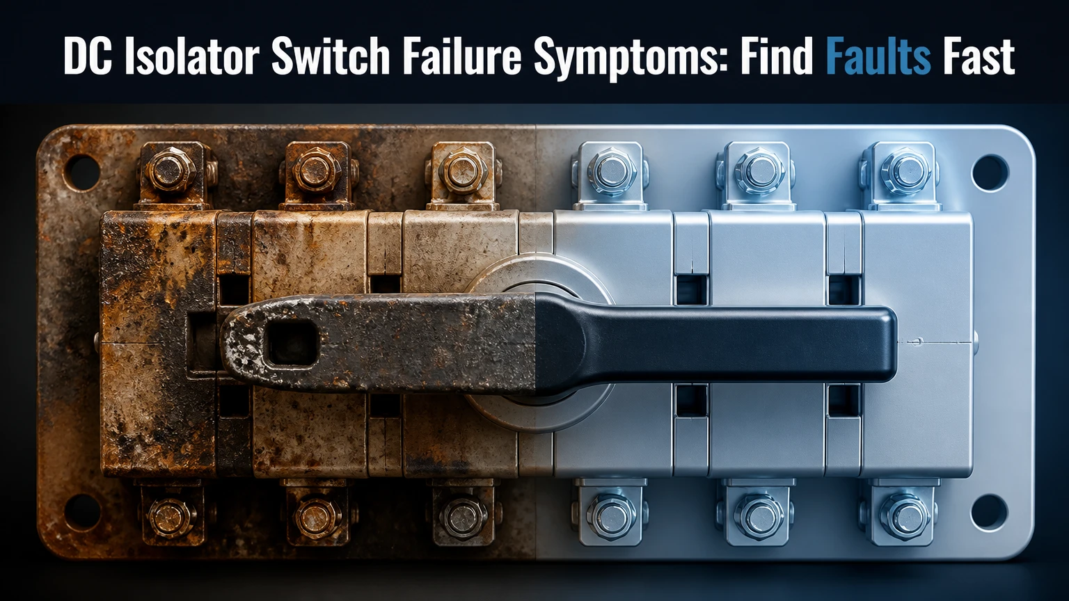
DC isolator switch failure symptoms include scorching, melted plastic, burning odor, abnormal heat, a stiff or loose handle, failed latching, inverter isolation alarms, and unexplained production loss. A damaged switch can remain electrically live when turned off, so visible damage or repeated faults require system shutdown and assessment by a qualified electrical professional.
Key Facts at a Glance
- A DC isolator must be rated for the system’s maximum DC voltage, current, pole arrangement, and switching duty.
- An AC circuit breaker or isolator is not automatically safe for photovoltaic or battery DC circuits.
- A switch marked OFF may still have welded contacts, so position alone never proves electrical isolation.
- Localized heating usually indicates resistance at a terminal, contact, fuse, or conductor rather than normal switch operation.
- Rooftop PV modules can continue producing hazardous voltage in daylight after the inverter and AC breaker are off.
- Burning odor, smoke, arcing, exposed copper, or a melted enclosure requires immediate professional escalation.
What Are DC Isolator Switch Failure Symptoms?
The clearest DC isolator switch failure symptoms are heat damage, a burning smell, mechanical resistance, an incorrect handle position, and repeated inverter faults. A healthy enclosure remains intact, the handle moves positively, and the switch operates within its manufacturer-defined duty without discoloration or abnormal temperature.
A field inspection should begin outside the enclosure. Look for brown or black plastic, blistering, cracks, deformation around cable entries, white oxidation on terminals, and insulation that has become hard or brittle. A chemical or burnt-plastic odor is an early warning because polymer damage can begin before visible smoke appears.
Mechanical changes provide a second diagnostic path. A rotary handle that feels gritty, stops between positions, or turns without a firm snap may indicate a broken cam, corrosion, displaced contact, or heat-distorted housing. A toggle that will not latch can also leave contacts only partly engaged, creating resistance and heat.
Electrical symptoms are less specific. “Isolation fault,” “earth fault,” “DC arc fault,” or low insulation resistance can originate in modules, connectors, cables, surge devices, or the inverter itself. The isolator remains a suspect when the alarm follows one switch or appears after rain, heat, switching, or visible enclosure damage.
| Symptom | Typical implication | Urgency | Safe user action |
|---|---|---|---|
| Blackened enclosure or smoke | Arcing, overheating, or carbon tracking | Immediate | Keep away and call emergency services if fire develops |
| Burning plastic odor | Polymer or insulation overheating | Same day | Stop normal operation and contact installer |
| Handle feels gritty or will not latch | Cam, contact, or housing damage | Same day | Do not force the mechanism |
| Repeated isolation fault | Insulation defect anywhere in DC system | Prompt diagnosis | Record fault time and weather conditions |
| Warm enclosure below nearby equipment temperature | Possible high-resistance connection | Prompt inspection | Do not open or touch exposed parts |
| Cracked gland or water inside box | Moisture ingress and corrosion risk | Prompt repair | Keep enclosure closed and dry externally |
How Does a DC Isolator Fail?
A DC isolator usually fails when a poor connection, moisture path, incorrect rating, or mechanical defect creates heat or prevents reliable arc extinction. Direct current does not provide the periodic current zero used by many AC switching devices, so a load-breaking DC switch needs an appropriate contact system and arc-control design.
The common sequence is straightforward. A loose terminal or damaged contact increases resistance. Current through that resistance produces heat according to the relationship (P=I^2R). For example, a 20 A string passing through only 0.05 ohms of unwanted resistance dissipates 20 watts at one small connection, enough to accelerate oxidation and plastic damage inside a confined box.
Thermal cycling worsens the connection. Daytime heating, nighttime cooling, conductor movement, and repeated expansion can reduce clamping force when installation torque, conductor size, or terminal preparation is wrong. Moisture then adds corrosion, while UV exposure makes outdoor plastics and seals less resilient.
A damaged contact can pit, warp, or weld closed. When a user later turns the handle, the mechanism may separate slowly or fail to create the designed contact spacing, allowing an arc to persist. Arc chutes, magnetic blowouts, contact geometry, and rapid spring action are device-specific; none can compensate for using a switch outside its certified application.
Why is a DC arc more difficult to interrupt?
A DC arc is difficult to interrupt because current continues in one direction instead of naturally passing through zero. Certified DC disconnectors lengthen, cool, split, or magnetically deflect the arc, but the result depends on voltage, current, polarity, circuit configuration, and the manufacturer’s tested utilization category.
IEC 60947-3 covers switches, disconnectors, switch-disconnectors, and fuse-combination units, while IEC 60364-7-712 addresses electrical installations containing photovoltaic systems. The product marking and installation design must agree. A generic “1000 V” label without a suitable switching category, pole configuration, or wiring diagram is not enough.
The arc hazard is greatest when a switch is opened under load or when internal damage slows contact separation. Never deliberately cycle a suspect PV isolator to see whether it sparks. A qualified technician uses the manufacturer’s procedure and suitable test equipment after establishing a safe isolation boundary.
How Hot Is Too Hot?
A precise universal temperature limit does not exist because ambient temperature, enclosure color, sunlight, load, terminal design, and manufacturer limits all affect readings. As a practical screening rule, a localized enclosure or terminal area above about 60°C under load deserves prompt investigation, while smoke, odor, discoloration, or a large temperature difference is more important than a single number.
Infrared thermometers can misread shiny metal and sunlit plastic. An electrician may use calibrated thermal imaging, contact measurements where permitted, and comparison with adjacent identical circuits under similar load. A single hot terminal beside cooler terminals is more suspicious than an entire enclosure warmed evenly by afternoon sun.
For commercial sites, a typical preventive program records images during high irradiance at least twice yearly and after corrective work. A temperature difference above 10°C compared with equivalent neighboring equipment is a useful investigation trigger, not a universal replacement specification.
| Observation under comparable load | Likely interpretation | Typical response time | Required next step |
|---|---|---|---|
| 35-50°C enclosure, no odor or damage | Possible ambient or solar warming | Routine | Compare with nearby units |
| 50-60°C localized rise | Early resistance or load concern | 1-7 days | Arrange qualified inspection |
| More than 60°C at one terminal | High-resistance connection possible | Same day | Remove from service under procedure |
| 10°C or greater difference from matching unit | Abnormal thermal imbalance | Same day to 7 days | Investigate torque, conductor, and contact |
| Melting, smoke, or active arcing | Imminent equipment or fire hazard | Immediate | Evacuate if necessary and call emergency services |
Why Does the Inverter Report an Isolation Fault?
An inverter reports an isolation fault when it detects insufficient resistance between a DC conductor and earth, but the alarm does not prove that the isolator itself failed. The fault may be in a PV module, cable, connector, junction box, surge protective device, battery, inverter, or water-contaminated enclosure.
The timing provides useful evidence. A fault that appears only after rain suggests moisture in connectors, glands, cable insulation, or a switch enclosure. A fault that occurs at high temperature may indicate insulation expansion, a damaged cable, or a component whose leakage increases with heat. A fault that follows one string points the investigation toward that string and its isolator.
Do not repeatedly reset the inverter or operate several disconnects at random. Record the exact code, time, weather, production level, and which equipment was recently serviced. A qualified technician can then isolate sections, measure insulation resistance using equipment appropriate to the system, and compare results with manufacturer and local code requirements.
Which Specifications Matter?
The correct DC isolator specification is determined by maximum system voltage, maximum circuit current, switching duty, number of poles, polarity requirements, enclosure environment, and conductor termination method. A 1,000 V device is not suitable for a 1,500 V circuit, and a current rating must be evaluated with temperature and installation derating.
PV string circuits often use devices in the 16-63 A range, while battery and industrial systems can require hundreds or thousands of amperes. Those figures are typical application ranges, not design defaults. The designer must calculate open-circuit voltage at the lowest expected temperature, short-circuit or maximum operating current, parallel-string effects, and continuous-duty conditions.
Look for a recognizable certification mark, a complete datasheet, a wiring diagram, a defined DC utilization category such as DC-PV2 where applicable, and a clear polarity instruction. IP66 or IP67 may suit exposed outdoor enclosures, but an IP rating does not excuse poor glands, incorrect mounting, condensation, or submerged installation.
| Specification | Typical rooftop PV example | Battery example | Why it matters |
|---|---|---|---|
| Maximum operating voltage | 600-1,000 V DC | 48-800 V DC | Must exceed calculated maximum voltage |
| Continuous circuit current | 13-32 A per string | 100-630 A system section | Determines contact heating and conductor size |
| Pole arrangement | 2 or 4 poles | 2, 3, or 4 poles | Must isolate required conductors and polarity |
| Enclosure protection | IP65-IP67 | IP54-IP66 | Matches rain, dust, washdown, and indoor conditions |
| Switching category | DC-PV2 or manufacturer-specified PV duty | DC-21B or specified battery duty | Confirms tested load-breaking performance |
| Operating temperature | Approximately -25 to 60°C | Approximately -25 to 70°C | Affects derating and mechanism reliability |
Can an AC Isolator Replace a DC Isolator?
An AC isolator should not replace a DC isolator unless the exact product documentation explicitly certifies that device for the circuit’s DC voltage, current, poles, polarity, and switching duty. AC devices often depend on current zero crossings and may not safely extinguish a sustained photovoltaic or battery arc.
The same principle applies in reverse. A DC-rated device may have unsuitable AC characteristics, so substitution in either direction requires documentation rather than appearance-based judgment. A switch with a similar handle, enclosure, and ampere marking can have a completely different internal arc path.
A circuit breaker also is not automatically an isolator. Protection against overcurrent, safe disconnection, visible isolation, and load switching are related but different functions. The single-line diagram should identify which device performs each function.
Are Battery and PV Isolators Interchangeable?
Battery and PV isolators are interchangeable only when the selected device is specifically rated for both the battery’s voltage and fault current and the installation’s switching conditions. Battery systems can deliver very high short-circuit current, while PV strings have different current behavior and often higher open-circuit voltage.
Battery disconnects may require DC short-circuit ratings, precharge arrangements, fuse coordination, bidirectional switching, or arc-flash boundaries that a small rooftop PV isolator does not provide. Lithium-ion battery systems also require compliance with the battery manufacturer’s service procedure and applicable local fire and electrical rules.
| Application | Typical electrical behavior | Common disconnect requirement | Frequent selection error |
|---|---|---|---|
| One PV string | High voltage, modest current | PV-rated two-pole or multi-pole switch | Selecting by current only |
| Parallel PV array | Higher combined current | Correctly configured multi-pole or combiner device | Ignoring parallel-string current |
| 48 V battery bank | Lower voltage, very high fault current | High-interrupting-capacity DC device | Using a small PV switch |
| High-voltage battery rack | 400-800 V DC, substantial fault energy | Battery-certified disconnect and protection | Omitting precharge or fuse coordination |
| EV or industrial DC bus | High current and frequent switching | Industrial switch-disconnector or MCCB | Applying residential PV ratings |
How Should a Suspect Isolator Be Handled?
A suspect DC isolator should be treated as energized until a qualified person proves otherwise with an approved isolation procedure and test instrument. Turning off the inverter’s AC breaker may stop conversion, but daylight PV modules and charged batteries can still energize the DC conductors.
Homeowners should not open the enclosure, loosen terminals, remove covers, or test terminals with a household multimeter. The back-of-hand technique is not a safe electrical test and can increase contact risk. Keep people away, avoid water, and contact the installer or an appropriately licensed electrician.
A professional workflow normally includes:
- Control the area. Stop access if there is smoke, crackling, exposed conductor, or active heat damage.
- Follow the system procedure. Use the site’s shutdown sequence for PV, battery, inverter, and AC equipment.
- Establish lockout and tagout. Prevent another person from re-energizing the system.
- Identify every energy source. Account for sunlight, batteries, capacitors, parallel strings, and backfeed paths.
- Prove the tester. Verify the instrument on a known source, test the circuit, then verify the instrument again.
- Inspect and test. Check torque evidence, insulation resistance, polarity, continuity, contact condition, and enclosure integrity as permitted.
- Replace damaged parts. A melted switch, carbonized plastic, welded contact, or heat-damaged conductor normally requires replacement, not cleaning.
- Document the result. Record device model, ratings, photographs, measurements, torque values, and commissioning checks.
What should a technician test?
A technician should test the isolator in the context of the complete circuit, not rely on continuity through an unloaded switch. Useful checks can include visual inspection, thermal comparison, voltage verification, insulation resistance, polarity, conductor termination, contact resistance, and functional operation according to the manufacturer’s instructions.
Insulation resistance testing can damage sensitive electronics if performed across connected equipment incorrectly. The inverter, optimizers, batteries, and surge protection devices may require disconnection or a specific test method. The product manual controls the procedure.
Which Installation Errors Cause Failure?
The most common installation errors are incorrect DC rating, poor terminal torque, damaged cable strands, water entry, wrong polarity on polarized devices, and leaving a switch to interrupt a load beyond its tested duty. These errors create either heat at the connection or an arc the device was not designed to control.
Terminal torque must come from the product manufacturer, not a generic value copied from another switch. Conductors need the correct stripped length, ferrules only where approved, intact strands, suitable cross-section, and strain relief. A torque record helps identify workmanship problems during later maintenance.
Cable glands should maintain the enclosure rating and prevent water tracking. Top-entry penetrations need suitable liquid-tight fittings and drainage considerations. Condensation can also form inside a sealed box when temperature changes, so enclosure placement and manufacturer ventilation instructions matter.
Polarized isolators may rely on a specified current direction for magnetic arc control. Reversing line and load or positive and negative connections can defeat that design. The device wiring diagram is authoritative.
Repair, Replacement, or Wider Investigation?
Replacement is usually safer than repair when a DC isolator has melted plastic, welded contacts, carbon tracking, cracked insulation, or a distorted mechanism. Cleaning a blackened contact does not restore the original creepage distance, dielectric strength, or arc-control geometry.
A switch that feels stiff but shows no heat damage may still need removal and bench assessment. Lubricating a sealed mechanism, forcing a handle, or tightening live terminals can create a new hazard. The technician should also inspect upstream and downstream conductors because heat can travel into insulation and connectors.
A product recall changes the decision. Record the manufacturer, exact model, batch or date code, installation location, and photographs, then check the manufacturer, electrical regulator, or national product-safety database. Replacing only one visible switch can miss a batch-wide defect or a repeated installation error.
How Much Does Replacement Cost?
A typical residential DC isolator replacement costs about $150-$400 for labor and access, plus roughly $25-$120 for a basic certified unit, but difficult roof access, testing, cable damage, battery shutdown, scaffolding, and emergency attendance can raise the total substantially. These are planning ranges, not quoted prices.
A straightforward replacement may take 1-2 hours after the system is safely isolated. A fault investigation can take longer because the electrician may need to test strings, inspect connectors, remove damaged cable, or coordinate an inverter and battery shutdown.
| Work item | Typical price range | Typical duration | Cost increases when |
|---|---|---|---|
| Basic residential isolator | $25-$120 | 15-30 minutes fitting | Higher voltage, poles, or certified brand required |
| Standard service call | $100-$250 | 1-2 hours | Travel or after-hours access applies |
| Complete replacement visit | $150-$400 labor | 1-2 hours | Roof access or retesting is difficult |
| Cable or connector repair | $100-$600 | 1-4 hours | Heat damage extends beyond the switch |
| Battery disconnect service | $250-$1,000+ | 2-6 hours | High fault current and shutdown controls apply |
| Commercial thermal survey | $300-$1,500 | 2-8 hours | Many strings, reports, or night work are required |
What Should Homeowners, Installers, and Facility Managers Do?
Homeowners should stop handling a damaged device and report exact inverter codes, odor, noise, weather, and photographs taken from a safe distance. Installers should verify the complete DC design, terminal work, product history, and recall status rather than replacing a switch without finding the initiating fault.
Facility managers benefit from documented inspections during high-load periods, especially after extreme heat, flooding, construction, or inverter modifications. A maintenance record should include thermal images, device model numbers, torque checks where safe, enclosure condition, and corrective-action dates.
DIY owners should limit work to noncontact observation and documentation. A high-quality brand does not make an incorrectly rated or incorrectly wired isolator safe, and increasing the ampere rating alone does not solve a polarity, voltage, enclosure, or fault-current mismatch.
Preventing Future DC Isolator Failures
Prevention starts with design verification and continues through commissioning and maintenance. Match the device to calculated voltage and current, follow the manufacturer’s torque specification, protect cable entries from water, and confirm polarity before energization.
A practical maintenance schedule includes visual checks every 6-12 months for residential systems, thermal inspection at least annually in demanding environments, and immediate review after inverter fault repetition or severe weather. Commercial systems often justify six-month thermal surveys where load, access, or fire consequence is high.
Three practitioner rules prevent many repeat failures:
- Investigate the hot connection, not only the hot switch. The terminal, crimp, conductor, and mating connector may share the damage.
- Treat recurring alarms as evidence, not nuisance messages. Resetting an inverter can hide a developing insulation defect.
- Use the product wiring diagram, not the handle label alone. Polarity and pole sequencing can determine whether arc suppression works.
The limitation is important: no symptom list can identify the failed component with certainty. Identical inverter alarms can arise from unrelated insulation faults, and infrared temperature alone cannot prove contact resistance. Safe diagnosis requires system-specific measurements.
FAQ
Can a DC isolator fail when the solar system is switched off?
Yes. A PV array can remain energized in daylight even when the inverter and AC breaker are off, and a battery can remain energized regardless of sunlight. An isolator can also have welded contacts that stay connected in the OFF position. Qualified personnel must identify all sources and verify isolation with an approved procedure.
Should a hot solar isolator be turned off?
Do not operate a hot, damaged, smoking, crackling, or distorted isolator unless the system’s emergency procedure specifically directs that action and a qualified person can perform it safely. A load-breaking operation may create an arc. Keep clear, prevent access, and contact the installer or emergency services if fire or smoke is present.
Can rain cause an isolation fault without damaging the switch?
Yes. Water can enter connectors, cable glands, junction boxes, module backsheets, or surge-protection components without obvious external switch damage. If an isolation alarm follows rain or disappears after drying, moisture is a strong clue, but the complete DC circuit still requires professional insulation testing.
How long do DC isolator switches last?
A certified, correctly installed isolator may operate for many years, but service life depends on switching frequency, load interruption, ultraviolet exposure, heat, moisture, torque stability, and product quality. A calendar age cannot override symptoms. Any melted housing, welded contact, failed latch, or repeated overheating justifies immediate assessment.
Is a DC isolator the same as a circuit breaker?
No. A DC isolator provides disconnection and may have a tested load-breaking function, while a circuit breaker also provides specified overcurrent protection. Some products combine functions, but the marking and datasheet must confirm both. A switch-disconnector does not automatically protect conductors from short-circuit current.
What information should I give the electrician?
Provide the isolator’s photographs, manufacturer and model, inverter fault code, installation age, recent weather, smell or heat observations, time of failure, and whether production changed. Do not remove the cover to obtain a model number. A photo taken from a safe distance is sufficient for initial triage.
The Bottom Line
DC isolator switch failure symptoms include abnormal heat, burning odor, discoloration, melted plastic, stiff or loose operation, failed latching, inverter isolation alarms, and unexplained power loss. These signs can indicate a high-resistance connection, moisture ingress, contact damage, incorrect rating, or a wider insulation fault.
Do not assume OFF means deenergized, do not substitute an AC isolator, and do not open a suspect enclosure yourself. If the switch is damaged, hot, smoking, or repeatedly associated with an inverter fault, stop normal operation and arrange qualified diagnosis. The safest repair is usually a correctly rated replacement combined with investigation of the cable, terminal, connector, enclosure, and complete DC circuit.