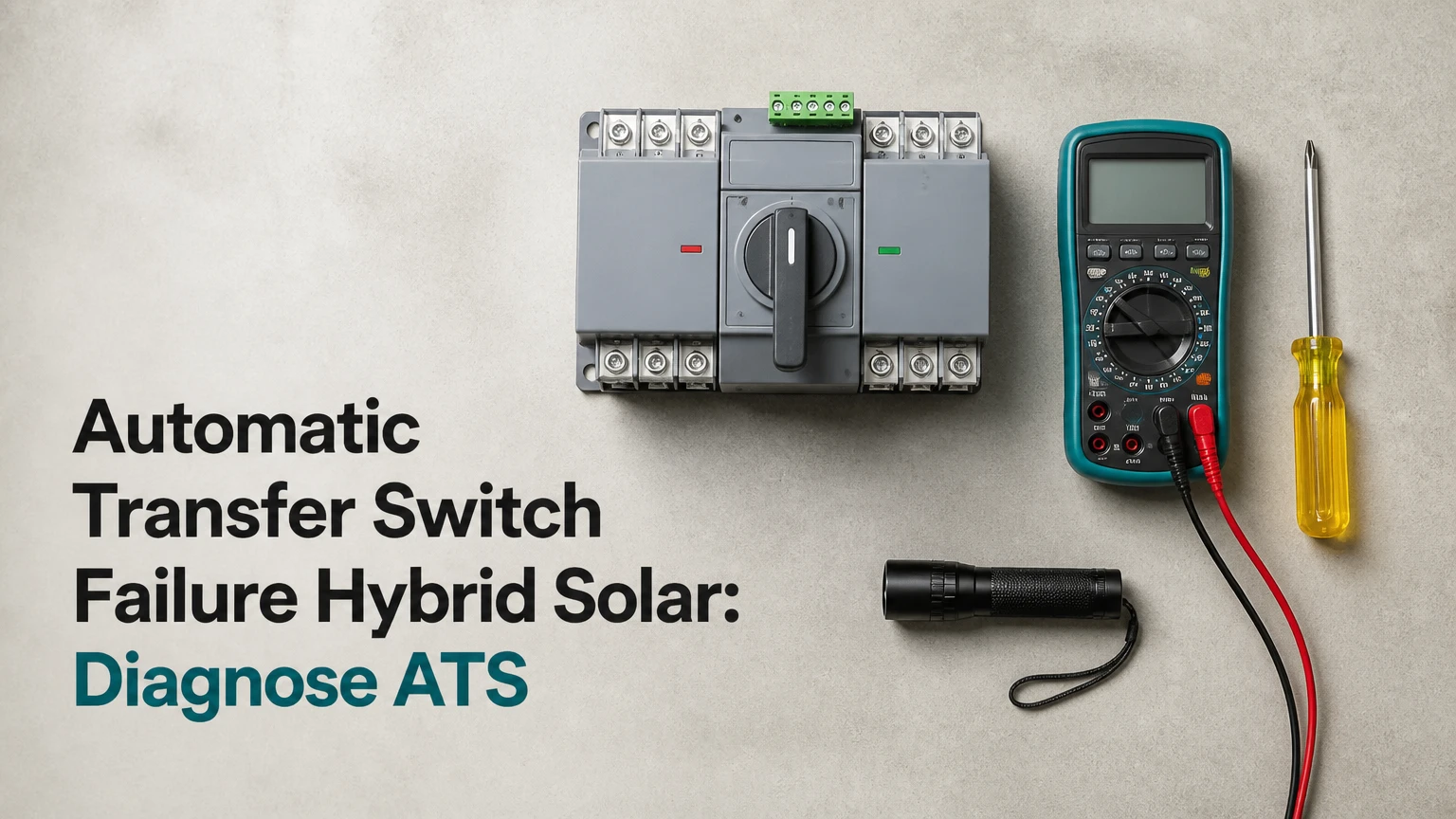
An automatic transfer switch failure in a hybrid solar system prevents safe transfer between the inverter-battery system, utility grid, and backup generator. Typical results include a blackout, failed battery charging, repeated clicking, nuisance tripping, or dangerous backfeed. The first priority is to isolate all sources and identify whether the fault is in the ATS, inverter, battery, generator, or wiring.
Key Facts at a Glance
- An ATS transfers electrical loads between separately controlled power sources; it does not repair an overloaded or defective solar inverter.
- A hybrid inverter may contain an internal transfer relay, making an external ATS unnecessary or unsafe in some designs.
- Rapid ATS clicking usually indicates unstable source voltage, insufficient inverter capacity, incorrect thresholds, or control-voltage loss.
- A welded contact, overheated lug, melted enclosure, or burning odor requires immediate shutdown and component replacement by a qualified electrician.
- Neutral switching and bonding depend on the inverter, generator, service equipment, and local electrical code; copying another installation can create shock or nuisance-tripping hazards.
- A typical residential external ATS costs $300-$1,500 installed, while higher-current or generator-rated systems can exceed $3,000.
What Does an ATS Do in a Hybrid Solar System?
An automatic transfer switch selects one approved AC source for a load panel and prevents incompatible sources from connecting together. In a hybrid solar installation, the sources may be a grid-forming inverter, utility supply, and generator, although the exact arrangement depends on whether the inverter backs up the whole home or only a critical-loads panel.
The ATS measures source voltage and frequency, applies programmed transfer delays, opens one source, and closes another. The switch also uses mechanical or electrical interlocking so grid and inverter outputs cannot accidentally parallel. A transfer switch is therefore a source-isolation device, not a battery charger, solar controller, or general-purpose power conditioner.
How does a hybrid solar transfer sequence work?
A normal open-transition sequence disconnects the active source before connecting the alternate source. The controller confirms source availability, waits through a time delay, energizes the alternate contactor, and then confirms that the load receives acceptable voltage.
Typical sequence values vary by manufacturer:
- The controller monitors voltage and frequency on both source inputs.
- A source falls outside its configured limits, or the inverter issues a transfer command.
- The ATS opens the active contactor.
- A short break occurs, commonly 30-100 milliseconds for a mechanical residential switch.
- The controller verifies the alternate source.
- The alternate contactor closes.
- The inverter, generator, or ATS controller records the transfer state.
A 20-50 millisecond delay is not universal. Contact travel, controller logic, source qualification, and programmed delays can produce a longer interruption. Closed-transition equipment may reduce interruption, but it requires compatible, synchronized sources and approval for the exact application.
Which ATS Types Fit Hybrid Solar?
Open-transition mechanical ATS units suit most residential systems when a brief interruption is acceptable. Static transfer switches transfer faster, but they cost more, generate heat through semiconductor devices, and require careful coordination with inverter waveform characteristics.
| ATS type | Typical transfer behavior | Hybrid solar application | Main limitation |
|---|---|---|---|
| Open-transition mechanical | 30-100 ms contact transfer | Residential backup panel | Brief interruption; contact wear |
| Closed-transition mechanical | Less than 100 ms overlap when synchronized | Approved utility-generator systems | Cannot safely overlap arbitrary inverter outputs |
| Static transfer switch | Commonly under 4-8 ms | Data rooms and sensitive commercial loads | High cost; heat and harmonic constraints |
| Inverter-integrated relay | Commonly 4-20 ms, model dependent | Hybrid inverter backup output | Limited by inverter rating and firmware |
The term “closed transition” needs special care in solar systems. A grid-tied inverter, generator, and battery inverter cannot simply overlap because all three produce voltage. Synchronization, phase angle, frequency, protection, utility permission, and manufacturer compatibility must be established first. A generic make-before-break switch can create severe fault current or damage inverter power electronics.
What specifications matter when choosing an ATS?
The correct ATS must match continuous current, voltage, poles, fault rating, source type, enclosure rating, control voltage, and transfer logic. A 100-ampere switch is not suitable merely because the average household load is 60 amperes; the service, feeder, overcurrent protection, and calculated demand must all agree.
| Specification | Typical residential range | Selection question | Failure consequence |
|---|---|---|---|
| Continuous current | 100 A, 125 A, 200 A | Does the switch match the feeder and protection? | Overheating or nuisance opening |
| System voltage | 120/240 V, single phase | Does the ATS match the inverter output? | Incorrect sensing or equipment damage |
| Poles | 2, 3, or 4 poles | Is neutral switching required? | Bonding conflicts or unsafe neutral paths |
| Short-circuit rating | 10 kA-22 kA typical | Does the rating meet available fault current? | Enclosure and contact failure |
| Control voltage | 12 VDC, 24 VDC, 120 VAC | Does the controller receive stable power? | Dead controller or chatter |
| Source qualification | Voltage and frequency limits | Are inverter and generator limits compatible? | Failed or repeated transfers |
The National Electrical Code, including Articles 700, 701, 702, and 705 in applicable installations, affects transfer equipment, optional standby systems, and interconnected power production. Local code adoption varies, so the equipment listing and authority having jurisdiction determine the final installation requirements.
Why Does Automatic Transfer Switch Failure Hybrid Solar Happen?
Automatic transfer switch failure usually results from contact damage, control-power loss, incompatible source settings, thermal stress, or incorrect neutral and grounding arrangements. A solar inverter adds another layer because its output can intentionally shut down during overload, low battery voltage, anti-islanding operation, or protection faults.
The most useful diagnostic distinction is source failure versus switch failure. If the ATS transfers correctly to a known-good utility source but the inverter source collapses under load, the ATS may be functioning normally. If both sources test correctly yet the contactor never moves, the ATS control circuit or mechanism becomes the primary suspect.
What symptoms indicate a failed ATS?
A failed ATS can produce a total blackout, power on only one source, repeated contactor operation, a blank display, heat discoloration, buzzing, or an error code. Symptoms must be interpreted with source measurements because a defective inverter can look identical to a defective transfer switch.
| Symptom | Likely cause | Confirming evidence | Immediate response |
|---|---|---|---|
| No transfer to grid | Blown control fuse, dead controller, failed coil | Valid grid voltage, no contactor command | Isolate sources; service controller |
| Rapid clicking | Source sag, low control voltage, chatter settings | Voltage changes during load transfer | Remove large loads; inspect settings |
| Stuck on inverter | Welded contacts or failed actuator | Contact position disagrees with command | Shut down; replace contact assembly |
| Heat or burning smell | Loose lug, overloaded conductor, arcing | Discoloration or thermal damage | De-energize all sources immediately |
| Inverter reboots | Transfer interruption or overload | Inverter event log matches transfer | Check load, transfer time, and firmware |
| Generator will not connect | Frequency, warm-up, or neutral mismatch | Generator outside acceptance window | Test generator independently |
A hum does not prove welded contacts. A contactor coil with low voltage may hum, chatter, and fail to pull in without any mechanical welding. Measuring control voltage while the transfer command is active separates a mechanical fault from a supply or controller fault.
Why Is the ATS Rapidly Clicking?
Rapid clicking occurs when the transfer controller repeatedly accepts and rejects a source. The usual mechanism is inverter voltage sag: the inverter picks up the load, voltage falls below the ATS threshold, the ATS returns to grid, the load is removed, and inverter voltage recovers.
Other causes include a weak 12- or 24-volt control supply, an undersized contactor coil transformer, generator frequency instability, loose terminals, an overly narrow voltage window, or insufficient return delay. Battery state of charge alone does not explain every event. A battery at 60% SoC can still have a low discharge-power limit, high cell temperature, or inverter current limit.
Recommended checks include:
- Compare inverter output voltage with no load and with the largest loads operating.
- Review inverter event logs for overload, low battery voltage, high temperature, and grid-loss events.
- Confirm the ATS undervoltage, overvoltage, underfrequency, and overfrequency settings against the equipment manual.
- Use a 10-30 second return delay only when the manufacturer permits it and the load can tolerate the interruption.
- Test air-conditioner, pump, compressor, and well-motor starting current separately.
- Inspect the control transformer and fuse for voltage drop during contactor operation.
An inverter that cannot support motor starting should receive load management or a soft starter, not merely a longer ATS delay. Delaying a transfer cannot create missing watts.
How Do You Diagnose an ATS Failure Safely?
A qualified electrician should diagnose energized transfer equipment because a hybrid solar system can remain live from the grid, photovoltaic array, battery, generator, and inverter output. Turning off the utility main does not necessarily make the enclosure safe.
Use this decision sequence:
- Record the symptom and event time. Photograph displays and record whether the failure occurs during grid loss, generator start, heavy load operation, or battery charging.
- Identify every source. List utility, PV, battery, generator, inverter output, and any AC-coupled solar inverter.
- Check the inverter and battery logs. Look for overload, low DC voltage, high temperature, grid-forming failure, and anti-islanding events.
- Verify source quality. A licensed technician should measure voltage and frequency at the ATS source terminals under load, comparing results with the manufacturer’s acceptance range.
- Inspect without touching energized parts. Look for heat marks, melted insulation, corrosion, carbon tracking, loose conduit, and a damaged manual handle.
- Test the control circuit. The technician checks control fuse continuity, coil resistance, command voltage, interlock operation, and auxiliary contacts.
- Test transfer under controlled load. Large motors and compressors should be disconnected or sequenced so their inrush does not obscure the basic fault.
- Verify the final state. The technician confirms source isolation, neutral continuity or switching, grounding, load voltage, and correct return-to-normal behavior.
A multimeter continuity test cannot prove that a contact is safe under load. A contact may show continuity while its surface is pitted, resistive, or thermally unstable. Thermal imaging under a representative load and a manufacturer-approved functional test provide stronger evidence.
When should an ATS be shut down immediately?
Shut the system down and obtain qualified service when the ATS shows smoke, melted plastic, visible arcing, a burning odor, severe discoloration, a welded contact, repeated fault-current operation, or an enclosure that is hot to the touch. Do not force a manual handle through resistance and do not bypass interlocks with wire, a screwdriver, or a temporary jumper.
A bypass switch can maintain service during planned maintenance, but bypass equipment must be listed, correctly rated, and operated in the sequence specified by its manufacturer. An improvised bypass can connect two sources or leave a conductor energized when the operator believes the system is isolated.
How Do Wiring and Neutral Errors Cause ATS Problems?
Neutral and bonding errors create circulating current, nuisance GFCI or RCD trips, objectionable current on grounding conductors, and dangerous touch voltage. The correct arrangement depends on whether the inverter output is separately derived, whether the generator switches its neutral, and where the system bonding point is located.
| Wiring issue | Typical field symptom | Electrical mechanism | Corrective direction |
|---|---|---|---|
| Unswitching neutral with incompatible source bonds | GFCI or RCD trips | Parallel neutral-current paths | Follow listed equipment diagram |
| Loose line lug | Heat, odor, voltage drop | Resistive connection under load | Re-terminate to specified torque |
| Reversed source conductors | Immediate fault or wrong polarity | Incorrect phase or neutral relationship | De-energize and correct wiring |
| Shared neutral on switched circuits | Unexpected live circuit | Incomplete source isolation | Reconfigure by code and design |
| Missing equipment grounding conductor | Chassis voltage risk | Fault current lacks low-impedance path | Install compliant grounding path |
| Undersized feeder or ATS | Thermal rise and nuisance trips | Current exceeds conductor or switch rating | Recalculate load and protection |
Terminal torque must follow the ATS label or installation manual. “Tight by feel” is not a specification, and over-tightening can damage strands or terminals just as under-tightening can create a hot joint. The electrician should use a calibrated torque tool and document the value.
What Changes When a Backup Generator Is Connected?
A generator requires source qualification, start and warm-up logic, cooldown timing, fuel capacity, neutral strategy, and often a dedicated control interface. Many generators produce unstable frequency during startup, so the ATS should not transfer loads until voltage and frequency remain within the approved window.
The generator may start after the inverter reaches a low-SoC threshold, after a grid outage, or after a load-management command. A typical sequence allows 5-15 seconds for generator startup and 10-30 seconds for warm-up, but the generator and ATS manuals control the actual values. Return to utility may include a 1-10 minute cooldown period.
| Generator factor | Typical value or range | Why it matters | Diagnostic clue |
|---|---|---|---|
| Startup delay | 5-15 seconds | Prevents nuisance starts | Generator starts after brief outage |
| Warm-up delay | 10-30 seconds | Stabilizes voltage and frequency | ATS refuses early transfer |
| Cooldown delay | 60-600 seconds | Protects engine and turbocharger | Generator runs after utility returns |
| Frequency target | 50 Hz or 60 Hz | ATS source acceptance | No transfer despite voltage |
| Generator rating | 5-22 kW residential typical | Limits connected load | Voltage collapses under demand |
| Fuel autonomy | 8-24 hours typical | Determines outage endurance | Generator stops during extended outage |
A generator that is electrically compatible with the ATS may still be incompatible with the inverter. Confirm dry-contact signaling, two-wire start, neutral switching, phase configuration, maximum generator input current, and whether the inverter accepts generator waveform distortion.
How Much Does ATS Repair or Replacement Cost?
A typical residential ATS diagnosis costs $150-$400, repair may cost $250-$900, and replacement commonly totals $600-$2,500 installed. A 200-ampere service, generator integration, difficult access, code corrections, or commercial fault ratings can raise the total above $3,000.
| Service or equipment | Typical equipment price | Typical labor or total | Normal timeframe |
|---|---|---|---|
| Control fuse or minor service | $5-$40 | $150-$400 total | 1-3 hours |
| Residential 100-125 A ATS | $300-$900 | $600-$1,500 installed | 3-6 hours |
| Residential 200 A ATS | $700-$1,800 | $1,200-$2,500 installed | 4-8 hours |
| Generator-rated ATS with bypass | $1,000-$3,000 | $2,000-$4,500 installed | 1-2 days |
| Static transfer switch | $1,500-$5,000 | $3,000-$8,000 installed | 1-3 days |
Prices vary by region, access, permit requirements, and whether the failed unit damaged feeders or the inverter. Replacing a contactor is economical when the enclosure, controller, insulation, and terminals remain sound. Heat-damaged plastic or carbonized buswork usually justifies complete replacement.
How Can ATS Failure Be Prevented?
ATS failure prevention combines correct sizing, compatible source settings, surge protection, load management, and periodic inspection. The highest-value preventive action is commissioning the transfer under realistic loads, including the starting current of compressors, pumps, and battery chargers.
| Preventive action | Recommended interval | Specific check | Failure prevented |
|---|---|---|---|
| Visual inspection | Every 6 months | Heat marks, odor, corrosion | Early thermal damage |
| Functional transfer test | Every 6-12 months | Source transfer and return | Stuck mechanism |
| Torque verification | Per manufacturer, often annually | Line and load terminals | Loose-lug heating |
| Event-log review | After every outage | Inverter and ATS alarms | Repeated overload |
| Generator exercise | Monthly, 15-30 minutes | Voltage, frequency, load response | Failed emergency start |
| Surge protection inspection | Annually and after storms | SPD indicator and grounding | Control-board damage |
Surge protective devices reduce transient risk but do not make an incorrectly bonded or poorly grounded system safe. Lightning protection, grounding electrode connections, conduit bonding, and service protection must be evaluated as a system.
An expert commissioning rule is to test the largest motor load separately before testing the whole backup panel. If the system fails only when an air conditioner starts, the transfer switch may be healthy while the inverter lacks surge capacity.
Which Alternatives Can Replace an External ATS?
An inverter-integrated transfer relay, listed interlocked manual transfer switch, critical-loads panel, UPS, or load-shedding controller can replace an external ATS in selected designs. No alternative is universal because each option changes transfer speed, capacity, maintenance, and source-isolation behavior.
| Alternative | Typical transfer time | Suitable load | Important limitation |
|---|---|---|---|
| Inverter-integrated relay | 4-20 ms | Inverter-backed critical panel | Limited by inverter output rating |
| Manual interlocked switch | 1-5 minutes | Planned or emergency source selection | Requires an operator |
| UPS | 0-10 ms | Computers, networking, controls | Limited runtime and output capacity |
| Critical-loads subpanel | 4-20 ms through inverter | Refrigeration, lights, communications | Excludes whole-home loads |
| Load-shed controller | 1-30 seconds | HVAC, water heating, pumps | Does not replace source isolation |
A UPS is better than a faster ATS for computers that cannot tolerate even a short interruption. A critical-loads panel is better than backing up a whole home when inverter capacity is limited. A manual transfer switch is useful as a service fallback, but it does not provide unattended transfer.
Which Solution Fits Each System?
The best solution depends on load size, source count, transfer tolerance, and the inverter manufacturer’s wiring architecture. A standard open-transition ATS fits a compatible residential generator installation, while a UPS or inverter-integrated relay better protects sensitive electronics.
| User situation | Preferred arrangement | Typical capacity or speed | Avoid when |
|---|---|---|---|
| Essential home circuits | Hybrid inverter and critical-loads panel | 5-15 kW, 4-20 ms | Whole-home motor loads exceed rating |
| Whole-home generator backup | Listed 100-200 A ATS | 30-100 ms | Inverter and generator cannot synchronize |
| Office networking equipment | Online UPS plus inverter backup | 0-10 ms output transfer | Runtime exceeds battery capacity |
| Remote homestead | ATS with manual bypass | 100-200 A, 3-6 hour service window | Bypass is not listed or maintained |
| Commercial critical load | Static transfer switch | Under 4-8 ms | Poor waveform or high fault current |
| Budget intermittent backup | Manual interlocked transfer | Operator-controlled | Automatic outage response is required |
A standalone ATS is not automatically safer than an inverter-integrated relay. The safer choice is the arrangement listed for the exact inverter, service configuration, grounding method, and source combination.
FAQ
Can a low battery cause an ATS to fail?
A low battery can cause the inverter source to disappear without physically damaging the ATS. The inverter may disconnect its output at a low-SoC, low-voltage, high-temperature, or discharge-power threshold, prompting a normal transfer to grid or generator. Check inverter logs and DC limits before replacing the switch.
Can an ATS backfeed the utility grid?
A correctly installed and listed ATS prevents backfeed by interlocking source contacts and isolating the nonselected source. Backfeed becomes possible when installers bypass interlocks, miswire line and load terminals, use an unsuitable closed-transition device, or connect an inverter output outside the approved transfer architecture.
Does a hybrid inverter always need an external ATS?
A hybrid inverter does not always need an external ATS. Many models contain an internal transfer relay for a dedicated backup output, while others require external switching for whole-home or generator applications. The inverter installation manual, service rating, and local electrical requirements determine the arrangement.
Why does my ATS work on grid but not on solar?
An ATS that works on grid but not on solar often receives an inverter output outside its voltage or frequency window, or the inverter cannot sustain the connected load. Test the solar source under load, review overload events, confirm neutral configuration, and verify that the inverter output is connected to the ATS source terminals correctly.
How long does an automatic transfer switch last?
A mechanical ATS commonly lasts 10-15 years in residential service, with rated life often expressed as 10,000-50,000 operations. Frequent transfers, motor inrush, dust, humidity, loose terminals, and high temperature shorten life. A switch with heat damage should be replaced regardless of its age.
Should I repair or replace a failed ATS?
Replace an ATS when contacts are welded, insulation is carbonized, the enclosure is melted, busbars are damaged, or the controller and contactor have suffered a severe surge. A fuse, auxiliary contact, or replaceable coil can sometimes be repaired when the main assembly remains mechanically and thermally sound.
The Bottom Line
Automatic transfer switch failure in a hybrid solar system is often misdiagnosed because the ATS, inverter, battery, generator, and wiring respond to one another. Isolate every source, verify voltage and frequency under load, inspect for heat damage, check inverter logs, and confirm neutral and bonding arrangements before replacing parts. Use only a transfer device listed for the specific solar, battery, utility, and generator architecture.