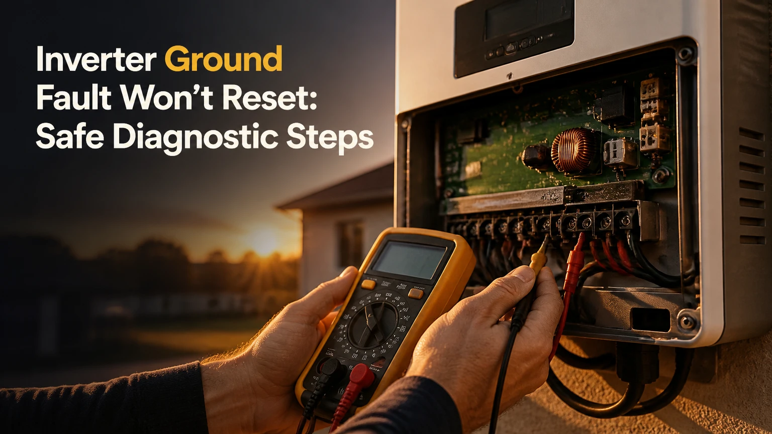
An inverter ground fault won’t reset when the inverter still detects unsafe current leakage or inadequate insulation resistance on the PV, AC, battery, or internal circuit. The alarm may result from wet connectors, damaged cable insulation, a failed surge-protection component, or a legitimate sensor fault. Repeated resets cannot repair the underlying condition.
Key Facts at a Glance
A persistent ground-fault alarm means the inverter’s protection system still sees an unsafe leakage path or failed self-test.
Rain, dew, condensation, and damaged connectors commonly create intermittent insulation faults that become persistent after water enters equipment.
A standard multimeter can miss insulation breakdown because its resistance test uses only a few volts.
A qualified technician must isolate the array before using a megohmmeter, and the inverter electronics must not receive an inappropriate insulation-test voltage.
A fault that remains after correctly isolating all external DC, AC, and battery circuits points toward an internal inverter or sensor problem.
Manufacturer manuals, local electrical rules, and the inverter’s voltage rating determine acceptable resistance thresholds and test procedures.
Why an Inverter Ground Fault Won’t Reset
An inverter ground fault won’t reset because the monitored leakage path remains below the inverter’s permitted insulation level, or because the fault-detection circuit itself has failed. The most useful first distinction is whether the alarm appears only in wet conditions, follows one PV input, or remains with every external circuit safely isolated.
Ground faults occur when a normally isolated conductor contacts grounded metal, wet insulation, a module frame, conduit, or another unintended path. In transformerless PV systems, small capacitive leakage can exist normally, but the inverter separates expected leakage from a dangerous insulation defect using programmed limits and current-sensor signals.
A reset can succeed briefly without proving the system is safe. For example, surface moisture may evaporate after noon, allowing the inverter to start, while a cracked connector continues admitting water during the next storm. A fault that returns at dawn is evidence, not a nuisance.
What does the alarm actually measure?
The alarm usually represents one of two measurements: insulation resistance before startup or residual current during operation. These measurements overlap in purpose but identify different stages of failure.
| Detection method | Measurement | Typical timing | What a failure suggests |
|---|---|---|---|
| Riso or isolation monitor | Resistance from live conductors to earth | Startup and reconnection | Wet, damaged, or degraded insulation |
| RCMU | Residual current imbalance | During operation | Current escaping to earth or frame |
| GFDI fuse or sensor | Grounded-conductor current path | Startup or operation | Grounded array conductor or protection-device action |
| Internal self-test | Sensor and switching response | Boot sequence | Failed relay, sensor, control board, or firmware issue |
Do not treat values such as 0.5 megohm, 1.0 megohm, 30 milliamps, or 300 milliamps as universal reset limits. SMA, Fronius, SolarEdge, Enphase, and other manufacturers use different algorithms, array configurations, and grid requirements. The inverter display, installation manual, and applicable code control the actual limit.
How Ground-Fault Detection Works
An inverter’s insulation monitor applies a controlled measurement to the DC system and calculates resistance to earth before connection; its residual-current monitor then watches for leakage while power flows. A low Riso value and a high residual-current event can produce similar user-facing messages, but their diagnostic paths differ.
The National Electrical Code addresses PV ground-fault protection in Article 690, while IEC 62446-1 defines documentation and verification practices for grid-connected PV systems. Neither reference creates one universal inverter reset threshold for every product. The equipment listing, manufacturer instructions, system voltage, and jurisdiction determine the valid procedure.
The inverter may also compare positive-to-earth and negative-to-earth behavior. A single grounded conductor can produce a clear fault, while balanced capacitive leakage from many modules may create nuisance trips only under certain array sizes or cable lengths.
Which symptoms identify the fault location?
Weather correlation is the strongest low-risk clue available to a homeowner. A fault at first light that clears in dry heat usually points toward moisture or condensation, while a fault that appears immediately after a wiring change suggests installation damage or connector misassembly.
| Symptom pattern | More likely area | Useful next evidence | Correct response |
|---|---|---|---|
| Alarm during rain or morning dew | Connector, junction box, module, conduit | Weather log and Riso trend | Qualified moisture inspection |
| Alarm after roof work | Cable, connector, conduit, racking | Work-order date and photos | Stop operation and inspect altered area |
| One input reports low insulation | PV string or optimizer branch | Input-level event history | Isolate that input using approved procedure |
| All inputs fail in dry weather | AC, battery, internal inverter, or shared wiring | Full event log and isolation test | Technician diagnosis, not repeated resets |
| Fault follows a battery connection | Battery cable, cabinet, or hybrid inverter | Battery and inverter event timestamps | Follow battery shutdown sequence |
| Alarm remains with external circuits removed | Internal electronics or sensor | Verified isolation record | Manufacturer-authorized service |
Before You Start: Safety and Preparation
Persistent inverter ground faults require a qualified solar electrician whenever covers must be removed, conductors must be disconnected, or insulation testing is required. PV modules can produce dangerous DC voltage whenever illuminated, even after an inverter display goes dark.
Do not open an inverter enclosure, unplug energized PV connectors, short string conductors, or apply a megohmmeter unless the person performing the work understands the equipment, arc-flash exposure, battery hazards, and local electrical requirements. NFPA 70E uses an electrically safe work condition process that includes disconnecting, locking out, verifying absence of voltage, and controlling re-energization.
| Preparation item | Typical value or requirement | Why it matters |
|---|---|---|
| Initial homeowner observation | 10-15 minutes | Records display code, weather, and visible damage |
| Professional diagnostic visit | 1-3 hours | Covers isolation, records, and basic tests |
| Required documents | Inverter manual, single-line diagram, event log | Identifies shutdown order and test limits |
| Minimum technician equipment | CAT-rated meter, lockout kit, PPE, approved connectors | Controls shock and reconnection risks |
| Insulation test equipment | Calibrated megohmmeter matched to system | Finds voltage-dependent leakage |
| Stop-work condition | Smoke, heat damage, arcing, water inside live gear | Requires emergency isolation and escalation |
A homeowner can photograph the display, note the exact code, check whether rain preceded the event, and look for obvious external damage from ground level. Those observations reduce diagnostic time without exposing the homeowner to live DC.
Step 1: Record the Alarm and Inspect Visible Areas
Record the exact fault code, timestamp, weather, inverter operating state, and affected input before changing anything. A code such as “Riso low,” “isolation fault,” “residual current,” or “GFDI” narrows the diagnostic path more effectively than a generic description of a failed reset.
Inspect only accessible, de-energized-looking external areas without touching conductors or removing covers. Look for cracked module glass, hanging cables, cable insulation against sharp racking, rodent damage, standing water, corrosion, burnt connector bodies, and conduit openings that face upward.
You will know this step produced useful evidence when the fault has a repeatable pattern linked to a location, weather event, or recent work. The common mistake is drying the visible equipment and calling the issue fixed, even though water may remain inside a connector or junction box.
Can rain make the fault permanent?
Rain can turn an intermittent insulation defect into a persistent ground fault by filling a cracked connector, wetting a pinched cable, or creating a conductive film across contaminated equipment. Dry weather may temporarily raise resistance above the trip threshold without removing the damaged insulation or failed seal.
| Weather or timing | Likely mechanism | Diagnostic value | Typical action |
|---|---|---|---|
| Heavy rain, immediate alarm | Water penetration | High | Inspect seals and connectors |
| Dawn alarm, afternoon recovery | Dew and condensation | High | Test during the failure period |
| Alarm after snowmelt | Water migration under modules | Medium to high | Inspect low points and junctions |
| Continuous fault in dry weather | Hard insulation failure | High | Perform controlled isolation testing |
| Alarm during hot afternoon | Thermal expansion or damaged cable movement | Medium | Inspect racking contact and cable tension |
Step 2: Isolate the System Using the Manufacturer’s Procedure
A qualified technician should isolate AC, DC, and battery sources in the order specified by the inverter manufacturer, then apply lockout and verify the absence of hazardous voltage. There is no universally safe instruction to switch every system’s AC breaker first, because hybrid inverters, rapid-shutdown systems, storage equipment, and service configurations differ.
The technician then separates external circuits from the inverter without interrupting energized DC under load. PV connectors are not ordinary plugs, and many are unsafe to disconnect while current is flowing. The person performing the work must use listed disconnects, approved tools, and the equipment manual.
Once the external circuits are safely isolated, the technician may perform the manufacturer-approved self-test or resistance checks. If the inverter reports a missing string rather than a ground fault, the evidence shifts toward field wiring, modules, or connectors. If the alarm persists with every permitted external source removed, internal failure becomes more likely.
You will know this step worked when the isolation record identifies which circuit changes the alarm and the inverter remains in the state prescribed by its manual. The common mistake is using the display’s reset command as a substitute for physical isolation.
Step 3: Test PV Insulation With a Suitable Megohmmeter
A megohmmeter detects insulation defects that an ordinary digital multimeter can miss because it applies a higher, controlled DC test voltage. The tester must be connected only to a fully isolated circuit, with the inverter, optimizers, rapid-shutdown devices, batteries, monitoring electronics, and other voltage-sensitive equipment protected or disconnected according to their manuals.
The test voltage depends on the array’s maximum system voltage and the manufacturer’s instructions. A 500-volt test may be appropriate for some 600-volt equipment, while 1,000 volts may apply to certain 1,000-volt systems, but the value must never be guessed from the inverter’s nominal operating voltage.
The technician normally tests each string or circuit to the equipment grounding system and records the positive-to-earth, negative-to-earth, and combined results where the equipment procedure requires them. Some modern module-level power electronics prohibit conventional megohmmeter testing across their inputs, so the component documentation determines the test boundary.
| Test target | Typical recorded result | Interpretation | Next decision |
|---|---|---|---|
| String A to earth | 25 MΩ | Strong insulation result in many systems | Compare with other strings |
| String B to earth | 0.18 MΩ | Low result requiring investigation | Sectionalize after safe discharge |
| Positive to earth | 1.4 MΩ | Moderate, system-dependent result | Compare manual threshold |
| Negative to earth | 0.22 MΩ | Suspect negative-side leakage | Inspect negative conductor path |
| Array with electronics attached | Uninterpretable | Electronics may distort or be damaged | Follow component procedure |
Resistance thresholds are not interchangeable across manufacturers. A value above 1.0 MΩ may be acceptable in one design but insufficient in another, while a high reading can still miss a fault that appears only when wet, hot, flexed, or exposed to operating voltage.
You will know this step produced useful evidence when the result is repeatable, recorded with test voltage and circuit identity, and compared with the manufacturer’s limit. The common mistake is testing through the inverter, which can damage surge devices or produce a meaningless reading.
Step 4: Sectionalize the Failing Circuit
Sectionalization locates a failed half-string, module, connector, or cable segment by testing smaller portions of the failing circuit. The technician disconnects only through approved interfaces, labels every conductor, waits for capacitive discharge, and tests each section under the same controlled method.
The practical sequence is to divide the suspect circuit into two sections, test both, then divide the failing section again. Four rounds can narrow a long string to a small group of modules, although connector layout and rooftop access determine the actual time.
A failed result may come from the module junction box, a damaged lead, an incompatible connector pair, a cable trapped under a clamp, or a connector that looks intact but has lost its seal. Replacing only the visibly wet part often fails because the insulation defect may be inside the mating connector or behind the module.
You will know this step worked when one section consistently produces the low-resistance result and adjacent sections pass under comparable conditions. The common mistake is moving connectors between circuits without labels, which creates new polarity and workmanship hazards.
Step 5: Inspect Modules, Connectors, and Cable Routing
PV field faults most often become solvable when electrical results are combined with physical evidence. A low resistance on the negative side, for example, becomes more informative when the negative cable is found crushed against a rail or when a connector hangs in a puddle.
Inspect module backsheets, junction boxes, cable clips, connector bodies, seals, conduit entries, and racking interfaces. Check whether cable loops drain downward, whether connectors rest on the roof, and whether dissimilar connector brands have been mated. Connector compatibility is a listing and installation issue, not a visual judgment.
| Field component | Failure mode | Visible clue | Repair decision |
|---|---|---|---|
| PV connector | Seal failure or cross-mating | Discoloration, moisture, loose lock | Replace matched listed pair |
| Module lead | Abrasion or rodent cut | Exposed conductor or flattened insulation | Replace lead or approved assembly |
| Junction box | Cracked seal or failed diode | Water marks, heat discoloration | Module or junction-box service |
| Cable clip | Excessive compression | White stress marks or pinching | Reroute with listed clips |
| Conduit entry | Missing gland or downward seal | Water trail inside enclosure | Replace gland and correct routing |
| Module backsheet | Delamination or puncture | Bubbles, cracks, exposed layer | Module evaluation or replacement |
Thermal imaging can identify hot connectors and bypass-diode problems when the array is operating under sufficient load. It is not a reliable standalone ground-fault test when the inverter remains locked out, because a non-operating array may not produce the thermal contrast needed to reveal the defect.
Step 6: Separate External Faults From Internal Inverter Failure
An internal inverter fault becomes more likely when the ground-fault alarm remains after all external PV, AC, and battery circuits have been isolated according to the manual, or when several unrelated inputs fail simultaneously in dry conditions. A service technician must still rule out shared grounding, neutral, communication, and shutdown wiring before condemning the inverter.
Common internal causes include a failed metal-oxide varistor, residual-current sensor, isolation relay, input board, control board, or moisture-damaged power stage. A blown surge-protection component may follow a lightning event, but replacing the protective part without finding the surge or wiring cause can produce another failure.
AC-side wiring can also confuse fault detection. Incorrect neutral-to-ground bonding, a failed transfer switch, generator wiring, backup-load wiring, or an improperly configured transformer may create a legitimate or apparent isolation problem.
Do not open the chassis to inspect a surge card unless the manufacturer authorizes the work and the technician is qualified for the stored-energy and arc-flash hazards. A service center may replace a board, but a complete inverter replacement can be more economical when parts are unavailable or the unit is near the end of its service life.
Which Fault Type Fits the Evidence?
The best repair path depends on whether the fault is moisture-related, mechanical, component-level, or internal. A weather-dependent low-resistance result calls for field repair, while a persistent alarm with correctly isolated inputs calls for inverter service rather than more string testing.
| Fault category | Typical evidence | Typical repair | Typical duration |
|---|---|---|---|
| Moisture ingress | Rain or dew correlation, corrosion | Replace connector, seal entry, correct drainage | 2-6 hours |
| Cable abrasion | Low resistance in a fixed dry location | Reroute or replace listed cable section | 3-8 hours |
| Module insulation failure | One module or junction box fails repeatedly | Replace module or approved component | 2-5 hours |
| AC or grounding configuration | Alarm follows transfer or backup operation | Correct wiring and commissioning | 2-8 hours |
| Internal inverter failure | Fault remains with external circuits isolated | Board repair or inverter replacement | 1-4 weeks |
| PID-related degradation | Multiple modules show gradual leakage and output loss | Module replacement or system-specific mitigation | 1-5 days |
Potential-induced degradation, or PID, should not be used as a default explanation for every low-insulation reading. PID is more plausible when several modules in a high-voltage string show gradual power loss and related leakage patterns over time; one wet connector with a sharply failing test points elsewhere.
Should you repair or replace the inverter?
Repair is usually preferable when the inverter is under warranty, the fault is a replaceable protection or control board, and parts are available within the manufacturer’s service program. Replacement becomes more practical when the unit is older, unsupported, repeatedly failing, or incompatible with current storage and rapid-shutdown requirements.
| Decision factor | Repair is favored | Replacement is favored |
|---|---|---|
| Equipment age | 0-8 years | 10-15 years |
| Warranty status | Active warranty | Expired warranty |
| Parts availability | Board available in 1-3 weeks | Obsolete board unavailable |
| Repair cost | Under 40% of replacement cost | Above 60% of replacement cost |
| System changes | Existing array unchanged | Battery or power upgrade planned |
| Failure history | First internal failure | Two or more failures in 24 months |
These percentages are practical decision rules, not code requirements. Obtain a written diagnosis before replacing an inverter, because a field insulation fault can destroy a replacement unit or cause the new unit to trip immediately.
What Do Diagnostics and Repairs Typically Cost?
Typical US diagnostic costs range from $150-$350 for a residential electrician visit and $300-$600 for specialized insulation testing; repair pricing increases with roof access, array size, replacement parts, permitting, and whether a second visit is required.
| Service or repair | Typical US cost | Typical time | Main price variable |
|---|---|---|---|
| Basic visual and electrical diagnosis | $150-$350 | 1-3 hours | Travel and access |
| String insulation testing | $300-$600 | 2-5 hours | Number of strings |
| Connector or cable repair | $200-$700 | 3-8 hours | Roof access and materials |
| Module replacement | $250-$800 per module | 2-5 hours | Module availability |
| Inverter board service | $500-$1,500 | 1-3 weeks | Part and labor availability |
| Residential inverter replacement | $1,500-$5,000+ | 1-4 weeks | Capacity, permitting, storage |
| Commercial inverter replacement | $5,000-$25,000+ | 2-8 weeks | Power rating and crane access |
These are typical planning ranges, not quotations. Utility-scale equipment, steep roofs, asbestos-containing roofing, emergency dispatch, and permitting can push costs well beyond the table.
Common Mistakes That Prolong the Fault
Repeated resets do not remove leakage, and they can obscure the timing evidence needed to identify a weather-dependent defect. The following mistakes appear frequently during residential and commercial troubleshooting.
- Using only a digital multimeter. A low-voltage ohms test may report an apparently healthy circuit even when insulation fails at the inverter’s operating voltage. Use a suitable insulation tester under a controlled procedure.
- Disconnecting PV connectors under load. DC arcs can persist because current does not cross zero like alternating current. Use the listed disconnect and manufacturer sequence before separating connectors.
- Testing through power electronics. Optimizers, rapid-shutdown devices, batteries, and inverter inputs can be damaged by an inappropriate Megger voltage. Establish the approved test boundary first.
- Treating drying as repair. A connector that dries in afternoon heat may fail again during the next rain. Replace compromised seals, connectors, cable sections, or junction components.
- Ignoring recent construction. Roof work, pressure washing, pest control, and module replacement can pinch or pull cables. Correlate the first alarm with work dates.
- Replacing the inverter first. A new inverter will also detect a genuine array fault. Prove the external circuits are healthy before approving replacement.
- Changing firmware before preserving evidence. Firmware may alter alarm wording or thresholds, but updating before recording event logs can remove useful diagnostic context. Save logs and follow the manufacturer’s update notes.
Situation-Based Troubleshooting
The fault clears after several dry hours
Treat a dry-afternoon recovery as an intermittent insulation fault, not a successful repair. Schedule testing while the array is wet or reproduce the condition only through an approved controlled method, because a dry test can miss the leakage path.
The fault began after heavy rain
Prioritize exposed connectors, conduit entries, junction boxes, low cable loops, and cracked module hardware. Do not spray water onto equipment to reproduce the fault. Photograph water marks and have the technician inspect seals before energization.
The alarm appears only with a battery connected
Hybrid systems can report a ground or isolation fault from the battery cabinet, battery cables, backup loads, or inverter DC bus. Follow the battery manufacturer’s shutdown procedure, which may include waiting for stored energy to discharge and isolating multiple disconnects.
The inverter resets but trips again immediately
An immediate recurrence usually indicates a hard fault, a failed sensor, or an unresolved configuration issue. Record the exact sequence and stop attempting resets until the technician identifies whether the alarm occurs during startup Riso testing or active residual-current monitoring.
How Do You Verify the Repair?
A repaired system should pass the manufacturer’s startup checks, show acceptable insulation results for every tested circuit, and operate without recurring ground-fault events under representative conditions. Verification also requires correcting the physical cause, documenting test values, and confirming that protective devices remain installed and functional.
The technician should record the inverter model, firmware version, fault code, affected circuit, test voltage, measured resistance, replaced components, connector type, and final commissioning result. For a commercial plant, compare post-repair Riso readings with historical SCADA data rather than relying on one pass message.
Operate the system through at least one normal startup and observe its event log. If weather caused the original failure, monitor the next rain or high-humidity period. A repair is incomplete when the alarm disappears only because the equipment has not yet encountered the condition that caused it.
FAQ
Can I reset an inverter ground fault myself?
A homeowner can acknowledge an alarm or perform the manufacturer’s external reset if the manual permits it, but a persistent ground fault requires professional diagnosis. Do not remove covers, disconnect live PV connectors, enter a battery cabinet, or use a megohmmeter without appropriate training and isolation controls.
Is a ground fault the same as a short circuit?
A ground fault is a connection or leakage path between an energized conductor and earth or grounded equipment. A line-to-line short circuit connects two energized conductors and can produce very high current. Both are hazardous, but inverter ground-fault monitoring may detect leakage before conventional overcurrent protection operates.
How long can a solar inverter run with a ground-fault alarm?
A solar inverter should not be operated with an unresolved ground-fault alarm unless the manufacturer explicitly identifies the message as a non-trip informational event. A persistent protection lockout is designed to prevent operation while hazardous leakage may exist, so bypassing it can increase shock, fire, and equipment damage risk.
Can high humidity cause a false ground-fault reading?
High humidity can produce a real leakage path across contaminated surfaces, wet connectors, or damaged insulation, even when the system appears dry later. The reading is not false merely because moisture caused it. However, a failed sensor or unsuitable threshold can also create nuisance trips, which requires manufacturer-level diagnosis.
Does a ground fault always mean the inverter is bad?
A ground fault does not automatically mean the inverter has failed. PV strings, module junction boxes, connectors, AC wiring, batteries, transfer equipment, and grounding configuration can all cause the alarm. The inverter becomes the leading suspect only after external circuits are safely isolated and the fault remains.
When should I call the installer instead of an electrician?
Call the solar installer or inverter manufacturer when the alarm involves Riso, isolation, GFDI, rapid shutdown, optimizers, batteries, firmware, or warranty service. Call a qualified electrician for suspected AC wiring, transfer-switch, grounding, or service-panel problems. Complex systems may require both specialists.
The Bottom Line
An inverter ground fault won’t reset because the inverter still detects unsafe leakage, inadequate insulation, or a failed detection circuit. Start with the event code and weather pattern, then have a qualified technician isolate the PV, AC, and battery circuits using the manufacturer’s procedure. A controlled insulation test can locate a field fault, while a persistent alarm with all external circuits removed points toward internal service. Do not force resets or replace the inverter until the fault location is proven.