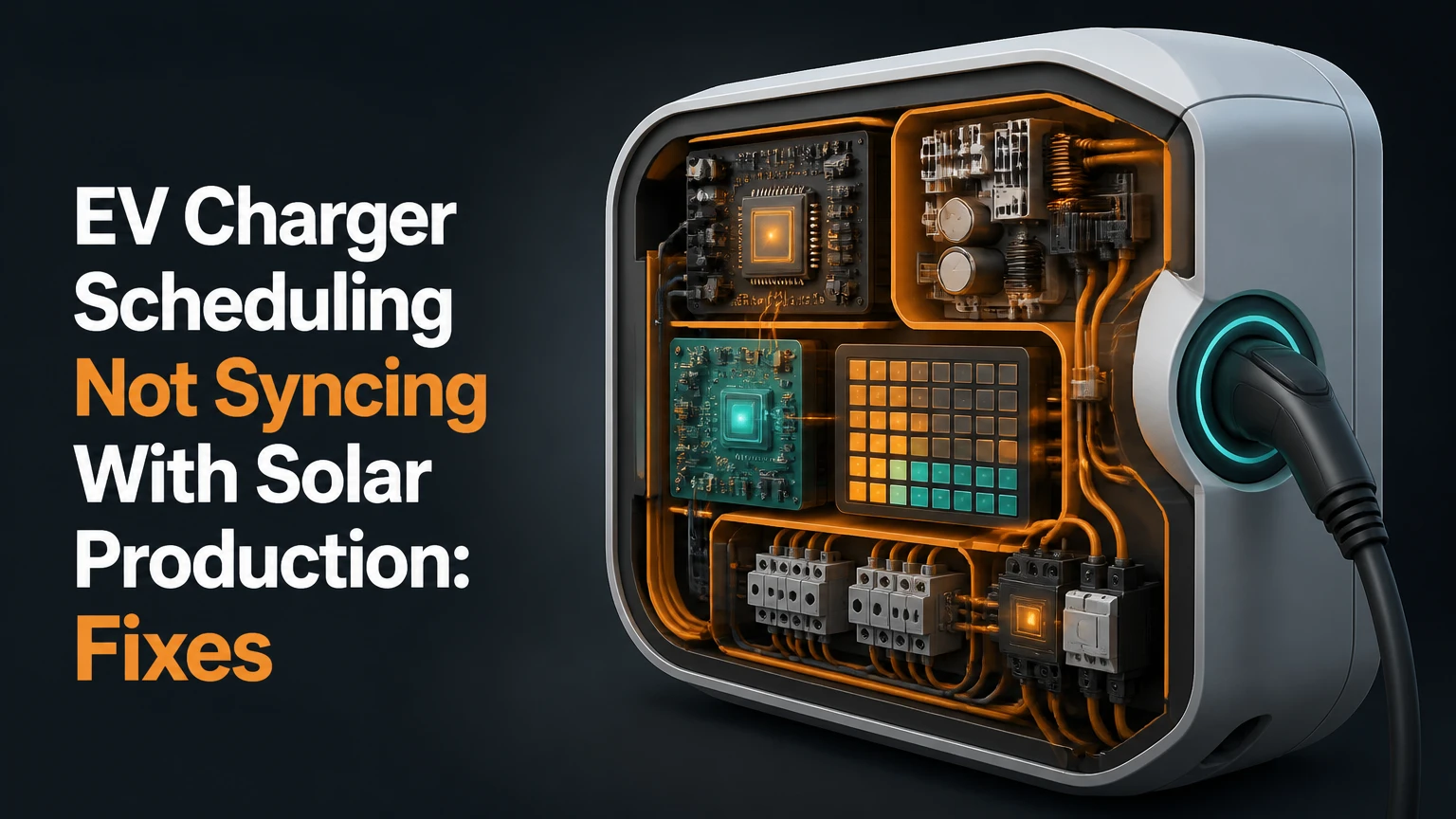
EV charger scheduling not syncing with solar production usually results from incorrect energy telemetry, competing schedules, a failed cloud connection, or insufficient surplus to meet the charger’s minimum current. Diagnose the system in that order: verify the home-energy readings, remove schedule conflicts, test CT-clamp direction, then adjust the solar threshold and integration.
Key Facts at a Glance
- Solar surplus equals photovoltaic production minus the home’s simultaneous electrical load.
- A standard AC EV charging session commonly needs at least 6 amps, or about 1.4 kW on a 230-volt single-phase circuit.
- A backward or incorrectly assigned CT sensor can make solar export appear to be household consumption.
- Vehicle timers, charger schedules, utility tariff rules, and energy-management commands can compete for control.
- Local CT-based control usually reacts in seconds, while cloud-to-cloud control commonly reacts in minutes.
- Solar-only charging is not always the cheapest option when a home has time-of-use electricity rates.
Why EV Charger Scheduling Not Syncing With Solar Production
EV charger scheduling not syncing with solar production is a control-loop failure, not necessarily a failed charger. The energy-management system must measure generation and demand, calculate surplus, and send a valid current command before the vehicle can follow the photovoltaic output.
The most useful first distinction is the observed behavior. A vehicle that charges at its maximum rate during midday likely has a control or schedule problem. A vehicle that never starts may have insufficient surplus, an active vehicle timer, an invalid pilot command, or a communication fault.
Solar production alone does not determine available charging power. A 7 kW photovoltaic array producing 5 kW may leave only 2 kW for the car if the house consumes 3 kW. A heat pump, electric water heater, battery inverter, or induction hob can change that balance within seconds.
The U.S. Department of Energy describes managed charging as shifting or modulating EV demand in response to grid conditions. Solar surplus charging applies the same principle locally, using export measurements instead of a utility signal.
What does the system calculate?
The controller estimates usable surplus with this basic relationship:
Usable solar surplus = solar generation – household load – battery charging demand – reserve margin
A controller may add a reserve margin of 0.2-1.0 kW to prevent grid imports during short production dips. Some products calculate net export directly at the service entrance, which is often more reliable than subtracting separate inverter and load readings.
How Does Solar EV Charging Work?
Solar EV charging works through measurement, calculation, communication, and current adjustment. The inverter or service CT sensors provide power data, an energy-management system calculates available surplus, and the EVSE changes the pilot current that the vehicle’s onboard charger may draw.
A typical local system samples power every 1-5 seconds. Cloud platforms may use readings delayed by 1-5 minutes because the inverter, platform, vehicle API, and charger each add processing time. That delay can cause brief grid imports even when the app appears to show solar production.
The charger does not directly control the battery cells. The electric vehicle supply equipment, or EVSE, advertises an allowable current through the control-pilot signal, and the vehicle’s onboard charger accepts a current within its own limits.
| System element | Measured or transmitted value | Typical response time | Common failure |
|---|---|---|---|
| Solar inverter | PV output in kW | 1-10 seconds locally | Stale inverter data |
| Main-service CT | Import or export in kW | 1-5 seconds | Reversed orientation |
| Energy-management system | Surplus calculation | 1-15 seconds | Wrong phase mapping |
| EV charger | Pilot current in amps | 2-30 seconds | Command rejected |
| Vehicle onboard charger | Accepted AC current | 5-60 seconds | Vehicle timer or sleep state |
Why does the charger sometimes import grid power?
A solar-aware charger may briefly import electricity because the controller reacts after production changes, household loads start, or cloud data arrives late. A sustained import of more than 0.2-0.5 kW during strong export usually indicates a configuration error, a reserve setting, or a failed control command rather than normal system behavior.
Which Solar-Charging Architecture Do You Have?
The architecture determines where synchronization can fail. A manufacturer-integrated system generally controls locally, a CT-based charger measures the service connection independently, and a cloud platform depends on internet access and permission to access both the vehicle and inverter.
| Architecture | Data path | Typical latency | Typical installed cost |
|---|---|---|---|
| Integrated inverter ecosystem | Inverter to charger over local network | Under 5 seconds | $1,200-$3,000 |
| CT-based smart EVSE | Main-service CT to charger controller | 1-10 seconds | $1,000-$2,400 |
| Cloud-to-cloud platform | Inverter API to platform to vehicle API | 1-5 minutes | $0-$300 initial, $0-$10 monthly |
| Home-energy controller | Inverter, meter, battery, and EVSE to EMS | 1-15 seconds | $1,500-$4,000 |
Examples include SolarEdge integrations, Enphase energy-management equipment, Tesla energy systems, Wallbox Eco-Smart configurations, Emporia monitoring, and third-party platforms such as ev.energy. Compatibility varies by region, firmware, vehicle, and subscription level, so a product name alone does not prove that dynamic solar control is supported.
Which architecture is most dependable?
Local measurement is generally more dependable than cloud scheduling because it avoids remote API permissions and vehicle wake-up delays. Cloud control is practical for tenants or low-cost retrofits, but it is a poor choice when exact surplus matching, outage operation, or rapid load response is the primary requirement.
What Should You Check Before Changing Settings?
Record the symptom, current charging amperage, solar output, grid import or export, and active operating mode before changing settings. A five-minute log taken at midday prevents a common diagnostic error: fixing a normal low-surplus pause as though it were a communications failure.
Use the following baseline conditions:
- Plug in the vehicle when solar production is at least 3 kW.
- Turn off large discretionary loads for two minutes.
- Record the inverter output and the home meter’s import or export value.
- Check the charger’s reported current and operating mode.
- Start one known load, such as a 1.5-2.0 kW kettle or heater, if safe.
- Capture screenshots showing timestamps from the inverter and charger apps.
Do not open a live distribution board or move a CT clamp unless the installation manual permits it and the circuit is safely isolated by a qualified electrician. Homeowners can compare app readings, disable timers, and reauthorize software; panel rewiring and phase verification belong to an electrician.
Step-by-Step: Restore Solar EV Charging
Step 1: Identify the Controlling Schedule
Disable vehicle-side charging timers, departure preconditioning rules, location-based rules, and manufacturer “charge by” targets. Set the EV charger to Plug and Charge, Solar, or an unrestricted mode while testing.
The success checkpoint is a charger app that shows an immediate charging request when adequate surplus exists. The common mistake is leaving a car timer active because the charger app appears to have priority. Many vehicles reject or delay an external request when their own schedule is inactive.
Step 2: Confirm Real-Time Telemetry
Compare three readings at the same timestamp: inverter production, household import or export, and charger power. A solar app showing 5 kW does not prove that 5 kW is available for charging because the house may consume 2.5 kW.
| Test condition | Expected reading | Fault indication | Likely correction |
|---|---|---|---|
| Midday, low household load | 2-8 kW PV output | Zero or stale output | Check inverter data link |
| Dryer or heater starts | Load rises 1.5-3.0 kW | Production rises instead | Investigate CT direction |
| EV begins charging | Export falls by charger draw | Export remains unchanged | Check charger meter path |
| Vehicle unplugged | Charger power approaches 0 kW | 1-7 kW remains reported | Check meter assignment |
The success checkpoint is a plausible power balance. The common mistake is comparing rounded app values from different timestamps, which can make a correctly functioning system look inconsistent.
Step 3: Test CT Clamp Direction and Location
A service CT normally measures the direction of current crossing the main conductors. During solar export, the energy monitor should report export, negative grid power, or a clearly positive solar-surplus value, depending on the manufacturer’s convention.
Ask an electrician to verify the arrow orientation, conductor assignment, phase mapping, and clamp placement. A clamp on only one conductor of a multi-phase service can produce a credible-looking but incomplete reading.
The success checkpoint is a controlled load test in which the measured household demand increases when a known appliance starts. The common mistake is flipping a clamp based only on a negative number, because some products intentionally display export as negative.
Step 4: Remove API and Network Failures
For cloud-connected systems, confirm that the inverter account, charger account, and vehicle account show current authorization. Reauthenticate the integration, update the app, verify the vehicle’s data-sharing permission, and check whether the manufacturer has imposed a service outage or changed API access.
A charger that can be started manually but ignores solar commands usually has a control-path problem. A charger that cannot be started manually has a broader connectivity, vehicle, or electrical fault.
The success checkpoint is a fresh timestamp and a visible remote command acknowledgment. The common mistake is repeatedly deleting and reinstalling the app without confirming that the correct account, region, and vehicle permissions were restored.
Step 5: Set a Realistic Minimum Solar Threshold
AC charging usually cannot modulate below approximately 6 amps. At 230 volts, that is about 1.38 kW for single-phase charging. At 240 volts, it is about 1.44 kW. A three-phase system drawing 6 amps per phase consumes approximately 4.1 kW at 400 volts.
| Charging arrangement | Minimum current | Approximate minimum power | Practical solar requirement |
|---|---|---|---|
| 230 V single phase | 6 A | 1.38 kW | 1.6-2.0 kW with buffer |
| 240 V single phase | 6 A | 1.44 kW | 1.7-2.0 kW with buffer |
| 400 V three phase | 6 A per phase | 4.16 kW | 4.5-5.0 kW with buffer |
| 230 V at 16 A | 16 A | 3.68 kW | 4.0-4.5 kW for stable operation |
Choose Solar Mix, Eco, or a similar blended mode if clouds repeatedly interrupt charging. A buffer of 0.2-0.5 kW and a pause delay of 60-300 seconds usually reduces rapid cycling, although exact settings depend on the charger.
The success checkpoint is a session that remains active through ordinary short cloud events without importing substantial energy. The common mistake is selecting pure solar with a zero buffer on a system whose output fluctuates around the minimum current.
Step 6: Verify the Pilot Command and Vehicle Response
If the charger displays 6-16 amps but the vehicle draws zero, the vehicle may be asleep, limiting current, rejecting the pilot signal, or reporting a delayed value. Stop and restart the session once, then inspect the charger’s fault code and the vehicle’s charging screen.
Do not repeatedly reset a charger that reports residual-current, insulation, overtemperature, or ground-fault errors. Those conditions require the manufacturer’s procedure and, in some cases, electrical testing.
The success checkpoint is agreement between the charger’s delivered power, the vehicle’s charging display, and the home meter’s reduced export. The common mistake is trusting the car’s estimated kW figure when it updates only every 30-60 seconds.
How Do You Interpret the Main Symptoms?
The symptom pattern often identifies the failed layer faster than the app error message. Use the table before changing hardware or purchasing another monitoring device.
| Observed symptom | Most likely cause | Confirming test | Corrective action |
|---|---|---|---|
| Full-rate grid charging at noon | Solar mode disabled or command path failed | Manual solar-mode status check | Restore mode and integration |
| No charging despite 4 kW export | Active vehicle timer or wrong CT sign | Disable all timers, inspect export sign | Correct hierarchy or CT setup |
| Start-stop cycling every 30 seconds | Surplus near minimum threshold | Watch surplus around 1.4 kW | Add buffer and pause delay |
| Charging begins five minutes late | Cloud polling or vehicle sleep | Compare timestamps | Use local control or accept delay |
| Charger pauses during three-phase export | Surplus below roughly 4.1 kW | Check phase current | Use single-phase mode if permitted |
| App shows solar production offline | Inverter API or Wi-Fi failure | Open inverter portal directly | Restore network or reauthorize |
| Grid import persists during charging | Wrong phase mapping or reserve setting | Compare service meter and CT data | Correct commissioning settings |
A counterintuitive fault is full-rate charging. Installers often focus on why charging stops, but maximum-rate grid charging means the charger may have lost the instruction to limit current, not that solar production is absent.
Which Operating Mode Fits Your Electricity Tariff?
Pure-solar charging maximizes direct photovoltaic consumption, while solar-mix charging improves reliability and time-of-use scheduling can cost less when overnight electricity is unusually cheap. The correct mode depends on export compensation, battery behavior, required departure energy, and the vehicle’s parking hours.
| Operating mode | Solar use | Grid exposure | Best fit | Main limitation |
|---|---|---|---|---|
| Pure solar | 80-100% during active sessions | Low during stable sun | High export penalty | Slow or interrupted charging |
| Solar mix | 50-100% depending on buffer | 0.2-2.0 kW during dips | Daily drivers | Some grid energy is intentional |
| Time-of-use schedule | 0-100% by tariff window | Concentrated in cheap hours | Overnight tariffs | May bypass daytime solar |
| Fixed current charging | 0-100% based on supply | Uncontrolled | Simple systems | No surplus response |
The practical rule is to protect the required departure charge first. A vehicle that needs 25 kWh by 7:00 AM should not rely on a winter solar window that historically provides only 12 kWh.
How Does a Home Battery Change the Diagnosis?
A home battery can make a correctly synchronized EV charger appear broken because the battery may absorb solar surplus before the EVSE receives an export signal. Battery reserve settings, backup mode, and discharge permissions must be checked alongside charger settings.
If the battery is set to charge first, the EV may remain paused until the battery reaches its target state of charge. If the battery is set to preserve backup capacity, the EMS may prevent EV charging even while the inverter reports substantial generation.
Check these values:
- Battery state of charge at the time of the failed session.
- Minimum reserve, commonly 10-30%.
- Solar export permission.
- EV charging priority in the energy-management system.
- Whether the charger is measured behind or ahead of the battery meter.
A useful test is to compare a sunny period when the battery is full with a period when it is below its charging target. If EV charging starts only after the battery fills, the hierarchy is functioning as configured.
What Does Solar EV Charging Cost to Retrofit?
A typical retrofit costs $1,000-$2,400 for a CT-based smart charger installation and $1,200-$3,000 for a manufacturer-integrated system. Cloud software can cost less initially, but recurring subscriptions, API limitations, and weaker control may reduce its value over several years.
| Retrofit item | Typical hardware cost | Typical labor cost | Typical duration |
|---|---|---|---|
| CT-enabled EVSE | $600-$1,000 | $400-$1,200 | 2-5 hours |
| Energy monitor and CT kit | $150-$500 | $250-$700 | 1-3 hours |
| Inverter integration gateway | $200-$800 | $300-$900 | 2-4 hours |
| Cloud charging platform | $0-$120 per year | $0-$250 setup | 30-90 minutes |
| Panel upgrade or load management | $500-$2,500 | $800-$3,000 | 4-10 hours |
These are typical planning ranges, not quotes. Conduit length, panel capacity, local permitting, three-phase wiring, detached garages, and network access can change the final price substantially.
When Should You Choose Local Hardware or Cloud Control?
Choose local CT-based control when stable second-level response, reliable export measurement, and operation during internet outages matter most. Choose cloud control when installation access is limited and occasional grid imports are acceptable.
| Decision factor | Local CT control | Integrated ecosystem | Cloud platform |
|---|---|---|---|
| Internet outage behavior | Usually continues | Usually continues | Often pauses or uses fallback |
| Response to cloud edge | 1-10 seconds | Under 5 seconds | 1-5 minutes |
| Brand compatibility | Often broad | Usually narrow | Depends on API contracts |
| Tenant suitability | Low to moderate | Low | High |
| Grid-import precision | 0.1-0.5 kW typical | 0.1-0.5 kW typical | 0.5-3.0 kW typical |
| Electrician involvement | Usually required | Required | Usually unnecessary |
Cloud control is not inherently defective. It is simply a poor match for users who expect the EV to follow every fast-moving change in PV output.
What Are the Most Common Repair Mistakes?
The most damaging mistake is changing several variables at once. Record the original threshold, mode, schedule, and CT readings, then change one control layer and retest under comparable sunlight.
Mistake 1: Treating inverter output as available surplus
A 6 kW inverter reading can coexist with a 4 kW household load. Use the grid meter or service CT reading to determine export, not generation alone.
Mistake 2: Setting the minimum below the electrical limit
A charger cannot reliably deliver 3 amps simply because the app accepts that number. Keep the lower limit at the manufacturer’s minimum, commonly 6 amps.
Mistake 3: Ignoring phases
Three-phase charging may require about 4.1 kW before it can start. A home with 2.5 kW of surplus may charge successfully in single-phase mode if the EVSE and local electrical rules support that configuration.
Mistake 4: Assuming a negative number proves reversal
Some applications define export as negative by design. Confirm the manufacturer’s sign convention with a controlled load test before moving a sensor.
Mistake 5: Reauthorizing only the charger
Cloud-to-cloud control can fail because the vehicle token expired while the charger connection remains healthy. Recheck all linked accounts, vehicle permissions, and regional API availability.
When Is an Electrician or Manufacturer Needed?
Call a qualified electrician for CT relocation, panel work, phase changes, breaker changes, new conductors, unexplained ground-fault trips, overheating, or readings that contradict the utility meter. Contact the charger or vehicle manufacturer when the pilot current is rejected, firmware reports a persistent fault, or a supported API integration stopped after an update.
Stop testing immediately if there is burning odor, visible heat damage, repeated residual-current protection trips, exposed conductors, water intrusion, or an electrical panel that feels hot. App-based troubleshooting cannot validate insulation resistance, conductor torque, protective-device operation, or code compliance.
Manufacturers may request the charger serial number, firmware version, vehicle model year, inverter model, screenshots with timestamps, CT configuration, and a description of the charging current. Supplying those details shortens support exchanges.
FAQ
Can solar charging work when the EV is asleep?
Solar charging can work with a sleeping EV when the EVSE maintains the charging session and the vehicle accepts external pilot changes. Cloud platforms may need to wake the vehicle, which can introduce delays or fail when telematics permissions, cellular coverage, or manufacturer servers are unavailable.
Why does my EV charge at night but not during the day?
Night charging with failed daytime charging usually points to a solar-mode configuration, CT-direction error, minimum-surplus threshold, or daytime vehicle timer. Night charging can succeed because the charger uses a simple fixed schedule that bypasses the failed solar telemetry path.
Does a larger solar inverter solve synchronization problems?
A larger inverter does not correct a backward CT clamp, expired API token, conflicting schedule, or incorrect phase mapping. More PV capacity helps only when the existing system regularly produces less than the EVSE’s minimum charging power.
Can I use a smart plug to control an EV charger?
A standard smart plug is unsuitable for controlling a Level 2 EV charger unless the equipment is specifically rated for continuous EV loads and installed under applicable electrical rules. Use an EVSE with pilot-current control, load management, and the required residual-current protection.
Is solar-only charging always cheaper than charging overnight?
Solar-only charging is usually cheaper when exported solar receives low credit and the alternative is retail-rate daytime charging. Overnight charging can be cheaper when a time-of-use tariff offers a very low off-peak rate or when solar charging forces significant grid imports during repeated cloud interruptions.
What information should I collect before contacting support?
Collect the EVSE and inverter model numbers, firmware versions, vehicle model year, charging mode, timestamps, solar output, grid import or export, charger current, CT location, and screenshots of active schedules. State whether the vehicle charges at full power, pauses, or refuses to start.
The Bottom Line
EV charger scheduling not syncing with solar production is most often caused by bad surplus data, a competing timer, a reversed or misassigned CT sensor, a failed cloud authorization, or a minimum-current threshold that the available solar cannot meet. Verify the power readings first, then isolate schedule control, test CT behavior, restore integrations, and add a sensible solar buffer.
A local CT-based or integrated energy-management system generally delivers faster and more reliable control than cloud-only scheduling. Pure-solar mode maximizes direct solar use, but Solar Mix or time-of-use charging can better protect departure readiness when sunlight is intermittent, household demand is high, or the home battery takes priority.