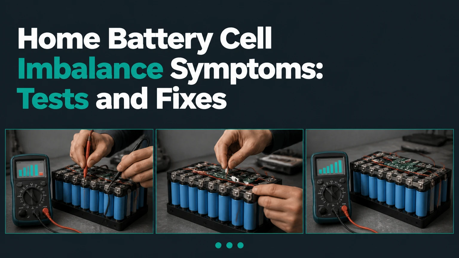
Home battery cell imbalance symptoms include a growing difference between individual cell voltages, sudden state-of-charge changes, reduced usable capacity, early charge termination, and premature low-voltage shutdown. A battery-management-system alarm, abnormal heating, or one cell reaching its voltage limit before the others strengthens the diagnosis, but solar, wiring, temperature, and software faults can look similar.
Key Facts
Cell imbalance means individual cells in one battery module have different states of charge or usable capacity.
A voltage spread is meaningful only when its charging state, temperature, chemistry, and measurement point are known.
Lithium iron phosphate batteries can show a small voltage change across much of their middle state-of-charge range, so voltage alone is a poor fuel gauge there.
A battery-management system can report imbalance without proving that a cell is permanently damaged.
Repeated high-voltage or low-voltage cutoffs usually indicate a capacity mismatch, weak cell, connection problem, or incorrect configuration.
Swelling, smoke, hissing, leaking electrolyte, or rapidly increasing temperature requires immediate shutdown from a safe location and professional service.
What Are Home Battery Cell Imbalance Symptoms?
The clearest home battery cell imbalance symptom is one cell or parallel group reaching a charge or discharge limit before the remaining cells. The battery may appear nearly full while charging stops early, or it may display 30% state of charge while shutting down under a modest load. Monitoring software often reveals the underlying spread before the homeowner notices a capacity problem.
A balanced pack has cells with similar voltage and usable capacity under the same conditions. Perfect equality is unrealistic because manufacturing variation, aging, temperature gradients, resistance, and measurement tolerances create small differences. The important pattern is persistent divergence, especially when the same cell repeatedly becomes the highest cell during charging or the lowest cell during discharge.
A single abnormal reading is weak evidence. A repeatable pattern across several charge and discharge cycles is much stronger.
| Observable symptom | Typical observation | Stronger imbalance clue | Alternative explanation |
|---|---|---|---|
| State-of-charge jump | 60% to 35% in 1-5 minutes | Repeats after moderate loads | Fuel-gauge calibration error |
| Early charging stop | Reaches 90-100% unusually quickly | One cell hits upper limit first | Charger voltage set too high |
| Early shutdown | Inverter stops at 20-50% displayed SOC | One cell reaches low-voltage cutoff | Cold battery or undersized cable |
| Reduced runtime | 10-30% less usable energy | Capacity loss follows one weak group | Higher household load |
| Voltage spread | 10-100+ mV during load or charge | Same cell remains outlier | Loose sense lead or connector |
Why does cell imbalance happen?
Cell imbalance develops when cells no longer store, release, or measure charge at the same rate. The most common causes are unequal aging, manufacturing variation, prolonged operation near full or empty, sustained heat, low-temperature charging, inadequate balancing time, and a weak parallel group.
Lithium battery packs contain series-connected cells or cell groups. Pack voltage is the sum of those series voltages, so the battery can show a normal total voltage while one cell is already near its upper or lower limit. The BMS protects the outlier, which can make the entire home battery stop even though most cells still have energy available.
Parallel cells behave differently. Cells connected in parallel share voltage and current, so an individual cell is harder to identify from external data. A failing parallel group can still appear as one series position in the BMS.
Common causes and their diagnostic clues
| Cause | Mechanism | Typical clue | Useful confirmation |
|---|---|---|---|
| Capacity aging | One cell group holds fewer amp-hours | Weak cell becomes lowest late in discharge | Controlled capacity test |
| High temperature | Heat accelerates resistance and degradation | Problem worsens above 35°C | Temperature log and thermal inspection |
| Low-temperature charging | Lithium plating risk increases below the maker’s limit | Charge blocked in cold weather | BMS temperature record |
| Loose sense connection | BMS receives false cell voltage | Reading jumps abruptly by 20-200 mV | Technician continuity and connector test |
| Failed cell or group | Higher internal resistance causes larger loaded drop | Same position fails under load | Cell resistance or load test |
| Configuration error | Incorrect voltage, capacity, or chemistry settings | Cutoffs occur at repeatable wrong values | Inverter and BMS settings review |
How much voltage spread is too much?
No universal voltage-spread limit identifies a defective home battery. As a practical screening rule, a lithium pack showing under 10-20 millivolts between cells at rest and near the same state of charge is often closely matched, while a persistent 30-50 millivolt spread deserves investigation and a repeated 100 millivolt spread under comparable conditions is a serious service clue.
The operating condition changes the meaning. During a high-current discharge, internal resistance temporarily creates a larger difference; the spread should shrink after the load stops. During the final stage of charging, a lithium iron phosphate cell can rise sharply while the pack is still balancing. Comparing a 100% charge reading with a 40% resting reading produces a misleading conclusion.
Use the battery maker’s specified cell limits first. Typical lithium-ion upper limits are about 4.20 volts per cell for many NMC designs and approximately 3.65 volts for many LFP cells, but the BMS may use narrower operational limits. Never alter those values to suppress an alarm.
| Chemistry or system | Nominal cell voltage | Common upper limit | Diagnostic caution |
|---|---|---|---|
| LFP lithium-ion | 3.2 V | About 3.65 V | Flat middle-voltage curve hides SOC differences |
| NMC lithium-ion | 3.6-3.7 V | About 4.20 V | Voltage tracks SOC more clearly than LFP |
| Lead-acid, 12 V bank | 2.0 V per cell | About 2.40-2.45 V per cell during absorption | Individual cell access is usually unavailable |
| High-voltage home battery | 3.2-4.2 V per cell | Manufacturer-specific | Installer software may be required |
Voltage spread is a screening measurement, not a capacity measurement. A cell can match voltage at rest yet collapse under load because its internal resistance is high.
Can monitoring software confirm imbalance?
Monitoring software can strongly indicate imbalance when it exposes individual cell or module voltages, temperatures, balancing status, and BMS event history. Software that reports only total pack voltage, current, and state of charge cannot confirm cell imbalance because those values conceal the weakest series position.
Look for labels such as “maximum cell voltage,” “minimum cell voltage,” “cell delta,” “balance active,” “high-cell cutoff,” and “low-cell cutoff.” Record timestamps rather than relying on a single live screen. The useful pattern is the same cell position repeatedly becoming the maximum during charging or the minimum during discharge.
State-of-charge estimates deserve caution. Many BMS units calculate SOC from coulomb counting, voltage, and a stored capacity value. If the capacity setting is wrong, SOC can jump even when cell matching is acceptable.
Victron Energy’s SmartShunt documentation states, “The SmartShunt measures the current flowing in and out of the battery.” That measurement improves energy accounting, but a shunt does not measure individual cell voltages. Cell-level evidence must come from the battery BMS or approved service software.
How can you check for imbalance safely?
A homeowner can check operating conditions, event logs, total voltage, temperatures, and visible damage without opening the battery enclosure. Individual-cell probing, cover removal, terminal torque checks, and live DC measurements belong to a qualified technician because residential batteries can contain lethal voltage and very high short-circuit current.
Use this sequence:
- Record the system state. Note battery model, chemistry, displayed SOC, charge or discharge current, ambient temperature, and inverter status.
- Capture BMS data. Save maximum cell voltage, minimum cell voltage, cell delta, battery temperature, and recent cutoff codes.
- Compare like with like. Take readings at similar SOC, current, and temperature, preferably after the battery rests for 30-60 minutes.
- Repeat the observation. Record readings during one controlled charge and one ordinary discharge. Do not create a heavy load to force a fault.
- Check external causes. Inspect approved user-accessible breakers, communication indicators, ventilation, and cable warnings without touching exposed conductors.
- Contact the installer. Supply timestamps, screenshots, firmware version, error codes, and the battery’s installation date.
You will have useful evidence when the same cell or module repeatedly diverges under comparable conditions. A common mistake is comparing readings from a cold morning and a warm afternoon, then treating the temperature effect as permanent imbalance.
What else causes the same symptoms?
Solar inverter limits, loose power cables, incorrect charge settings, cold-temperature protection, a defective temperature sensor, and inaccurate SOC calibration can all imitate cell imbalance. The battery is more likely to be involved when individual cell data identifies a repeatable outlier, while system-level symptoms point first to the inverter, wiring, or settings.
| Symptom pattern | More likely battery cause | More likely non-cell cause | First check |
|---|---|---|---|
| Battery stops only below 5°C | Cold lithium charging protection | Outdoor sensor placement | BMS temperature and manual |
| Whole pack voltage sags together | High load or depleted pack | Undersized cable or loose terminal | Load current and installer test |
| SOC jumps after reboot | BMS recalculation | Firmware or shunt calibration | Event log and SOC settings |
| Charging stops at the same total voltage | High cell or wrong cutoff | Charger configuration | Individual cell maximum |
| App loses the battery intermittently | BMS communication fault | CAN/RS485 cable or gateway | Communication status |
| Solar output is jagged before battery charging | No cell evidence | Cloud, shade, MPPT, or inverter | Compare PV and battery graphs |
The supplied Google overview describes photovoltaic fluctuation, including clouds, MPPT tracking, string inverters, microinverters, panel temperature, soiling, and DC cable faults. Those are valid solar-system topics, but they do not establish home battery cell imbalance. A jagged solar graph can reduce charging energy without any defective cell.
How does battery chemistry change the diagnosis?
Battery chemistry changes the useful voltage range, balancing behavior, temperature limits, and meaning of state-of-charge readings. LFP systems commonly need a controlled period near the upper charging region for passive balancing, whereas NMC packs have a steeper voltage curve but stricter energy and thermal management requirements.
LFP voltage remains relatively flat through much of its middle SOC range. Consequently, a 3.30-volt reading does not reliably distinguish a moderately full cell from another cell with substantially different remaining capacity. Near the top and bottom of the curve, small voltage changes become more informative.
Lead-acid banks show imbalance through unequal specific gravity, resting voltage, heating, or chronic undercharge, but most sealed home systems do not expose individual cells. Equalization charging is chemistry-specific and can damage lithium batteries. Never apply a lead-acid equalization procedure to a lithium pack.
Which readings matter by chemistry?
| Battery type | Most useful homeowner data | Typical balancing method | Do not do |
|---|---|---|---|
| LFP | Cell delta, temperature, upper cutoff history | Passive BMS balancing near full charge | Raise voltage beyond the manual |
| NMC | Cell delta, temperature, resistance trend | BMS-managed balancing | Disable thermal or overvoltage protection |
| AGM lead-acid | Rest voltage, charge voltage, runtime | Charger absorption and maintenance cycle | Add water to sealed AGM cells |
| Flooded lead-acid | Specific gravity, electrolyte level, rest voltage | Controlled equalization if specified | Equalize without ventilation and PPE |
Can charging or balancing repair imbalance?
Balancing can correct a small state-of-charge mismatch, but balancing cannot restore capacity to a degraded cell. Passive balancing commonly removes a small current from the highest cell, so a large mismatch may require many hours or several complete manufacturer-approved cycles; active balancing transfers energy between cells and remains a specialist function.
A safe corrective path starts with the manufacturer’s instructions. Confirm that the battery is within its permitted temperature range, use the approved charger profile, allow the BMS to complete its normal balancing process, and monitor for repeated cutoff events. Do not increase charge voltage, bypass the BMS, parallel unmatched batteries, or connect a bench charger directly to individual cells.
| Condition | Likely response | Typical timeframe | Decision point |
|---|---|---|---|
| 10-20 mV transient spread | Observe and log | 1-3 cycles | No repair if it settles |
| 30-50 mV persistent spread | Approved full-charge balance | 1-7 days | Escalate if unchanged |
| 100+ mV repeated spread | Professional diagnosis | Same week | Avoid forced cycling |
| One cell hits cutoff repeatedly | Cell or group testing | 1-3 service visits | Warranty or replacement review |
| Heat, swelling, smoke, odor | Immediate isolation | Immediate | Emergency service |
A common practitioner rule is simple: never “fix” a BMS alarm by widening the alarm threshold. The alarm may be the only protection preventing an overstressed cell from being charged or discharged further.
When should you stop using the battery?
Stop using a home battery immediately when the enclosure swells, becomes unusually hot, emits smoke or a solvent-like odor, makes hissing or popping sounds, leaks fluid, or shows rapidly escalating temperature. Keep people away, avoid touching the battery, and follow the manufacturer’s emergency procedure and local fire-service guidance.
For a non-thermal imbalance, stop forced charging and heavy discharge when the BMS repeatedly reports high-cell or low-cell protection, when the inverter cuts out at unexpectedly high SOC, or when the cell spread grows rapidly. If the battery is indoors, maintain clear access and do not obstruct ventilation.
Do not open a sealed home battery. Lithium packs can retain hazardous energy after the inverter is switched off, and a photovoltaic array or backup circuit may continue energizing parts of the installation. A qualified installer should isolate the battery according to the manufacturer’s sequence.
How much does diagnosis or repair cost?
Typical residential diagnostic visits cost about $150-$400, while module, BMS, or pack replacement can range from several hundred dollars to several thousand dollars depending on system voltage, warranty status, labor access, and manufacturer policy. Cell-level repair is often unavailable for certified home batteries because the enclosure, BMS, and warranty are integrated.
These figures are practical North American service ranges, not universal tariffs. High-voltage systems, remote locations, electrical permits, and emergency callouts increase the total.
| Service or outcome | Typical cost range | Typical duration | Main price variable |
|---|---|---|---|
| Remote log review | $0-$150 | 15-60 minutes | Installer warranty policy |
| On-site diagnosis | $150-$400 | 1-3 hours | Travel and system voltage |
| Communication repair | $100-$500 | 1-4 hours | Cable, gateway, or firmware |
| BMS or module replacement | $500-$2,500 | 2-8 hours | Manufacturer and pack design |
| Complete home battery replacement | $5,000-$18,000 installed | 1-2 days | Capacity, permits, and labor |
Warranty terms often matter more than repair economics. Provide the serial number, installation date, alarm history, cell screenshots, and evidence that the system used the approved settings before authorizing paid cell work.
How do you prevent recurring imbalance?
Prevent recurring imbalance by using the manufacturer’s charge profile, maintaining the specified temperature range, avoiding prolonged storage at an extreme SOC, keeping firmware and communications current, and investigating every repeated BMS cutoff. Battery health improves when the pack operates within its permitted limits rather than being repeatedly forced to its maximum output.
Follow the battery manual for storage SOC because recommendations differ. Many lithium manufacturers specify a partial SOC for storage, while backup systems may remain near full to preserve emergency capacity. The installer should also verify cable torque, conductor sizing, grounding, ventilation, and inverter compatibility during commissioning.
Do not mix batteries with different ages, firmware, chemistry, capacity, or BMS versions unless the manufacturer explicitly approves the combination. Parallel packs can hide a weak unit because the healthy pack temporarily supplies current.
Which system architecture makes diagnosis easier?
A battery with user-visible cell telemetry makes imbalance easier to identify than a system reporting only pack voltage and SOC. Modular batteries can simplify replacement when the manufacturer supports module-level service, while sealed high-voltage systems may require an authorized technician and proprietary software.
| Architecture | Cell visibility | Typical service path | Main limitation |
|---|---|---|---|
| Low-voltage DIY LiFePO4 | App may show each cell | Owner logs, specialist testing | Exposed high-current wiring risk |
| Sealed low-voltage battery | Pack data only | Installer or manufacturer | Weak cell may remain hidden |
| Modular high-voltage battery | Module data, sometimes cells | Authorized service partner | Proprietary tools and isolation |
| AC-coupled battery | Battery and inverter logs | Separate battery and inverter diagnosis | Two controllers can create misleading symptoms |
| DC-coupled battery | Shared solar-battery controls | Installer checks MPPT and BMS together | PV faults can resemble battery faults |
The architecture does not determine battery quality. A premium system with poor configuration can perform worse than a simpler system installed within its electrical and thermal limits.
What are the most common diagnostic mistakes?
The most common mistake is declaring imbalance from a total pack-voltage reading. Total voltage cannot identify which series cell is abnormal, and it can look normal while one cell approaches a protection limit.
Other frequent errors include:
- Comparing cell voltages at different SOC levels.
- Reading a cold battery immediately after charging.
- Treating a transient loaded spread as permanent capacity loss.
- Resetting the inverter before saving BMS event history.
- Replacing a battery before checking a loose sense connector or communication cable.
- Using a generic lithium charger with the wrong chemistry profile.
- Disabling high-voltage, low-voltage, or temperature protections.
- Assuming a solar production dip proves battery failure.
- Charging an LFP battery below the manufacturer’s minimum temperature.
- Installing a replacement module without matching firmware or capacity.
One useful field rule is to separate three measurements: voltage at rest, voltage under load, and recovered voltage after the load ends. A weak cell usually shows a disproportionate loaded drop, while a loose measurement connection may jump abruptly or behave inconsistently.
FAQ
Can a home battery work with one weak cell?
A home battery may continue operating with one weak cell until the cell reaches a BMS limit first. The usable pack capacity then follows the weakest series group, so runtime falls and shutdowns become more frequent. Continued operation can increase stress; an installer should test the battery rather than bypassing the protection.
Do balancing chargers fix lithium home batteries?
Balancing chargers can correct a state-of-charge mismatch when the cells remain healthy and the battery maker permits that procedure. They cannot restore lost capacity, repair internal resistance, or safely replace the BMS. Use only the approved charger and profile, because overcharging lithium cells can create a fire hazard.
Why does my battery say 100% but shut down?
A battery can display 100% when its coulomb counter is full while one cell reaches the upper voltage limit prematurely. Incorrect capacity settings, SOC calibration, high resistance, cold conditions, and charger configuration can produce the same result. Individual-cell data and event history distinguish these causes.
Can solar panel fluctuation cause cell imbalance?
Solar panel fluctuation does not directly prove cell imbalance. Clouds, MPPT behavior, shading, soiling, inverter clipping, or loose PV wiring can make charging power unstable, while repeated high-cell events identify a battery-side issue. Compare the solar power graph, battery current, cell delta, and BMS alarms on the same timestamp.
How long can a balanced home battery last?
A home lithium battery commonly has a design life of roughly 10-15 years or several thousand cycles, but usable life depends on temperature, depth of discharge, charge rate, and time at high SOC. A battery can remain functional beyond that period while losing capacity and showing greater cell divergence.
Should I replace the whole battery for imbalance?
Replace the whole battery only after confirming that the imbalance comes from a failed cell group, inaccessible module, or unsupported repair condition. A warranty provider may replace one module or the complete pack. Faulty wiring, calibration, firmware, or temperature sensing can often be corrected without replacing the battery.
The Bottom Line
Home battery cell imbalance symptoms are best confirmed by a persistent cell-voltage outlier, repeatable high-cell or low-cell cutoffs, and reduced usable capacity under comparable temperature and load conditions. A homeowner can safely document BMS data and external conditions, but should not open the enclosure or override protections. Balance only within the manufacturer’s procedure, and escalate rapidly when heat, swelling, odor, smoke, or repeated protection events appear.