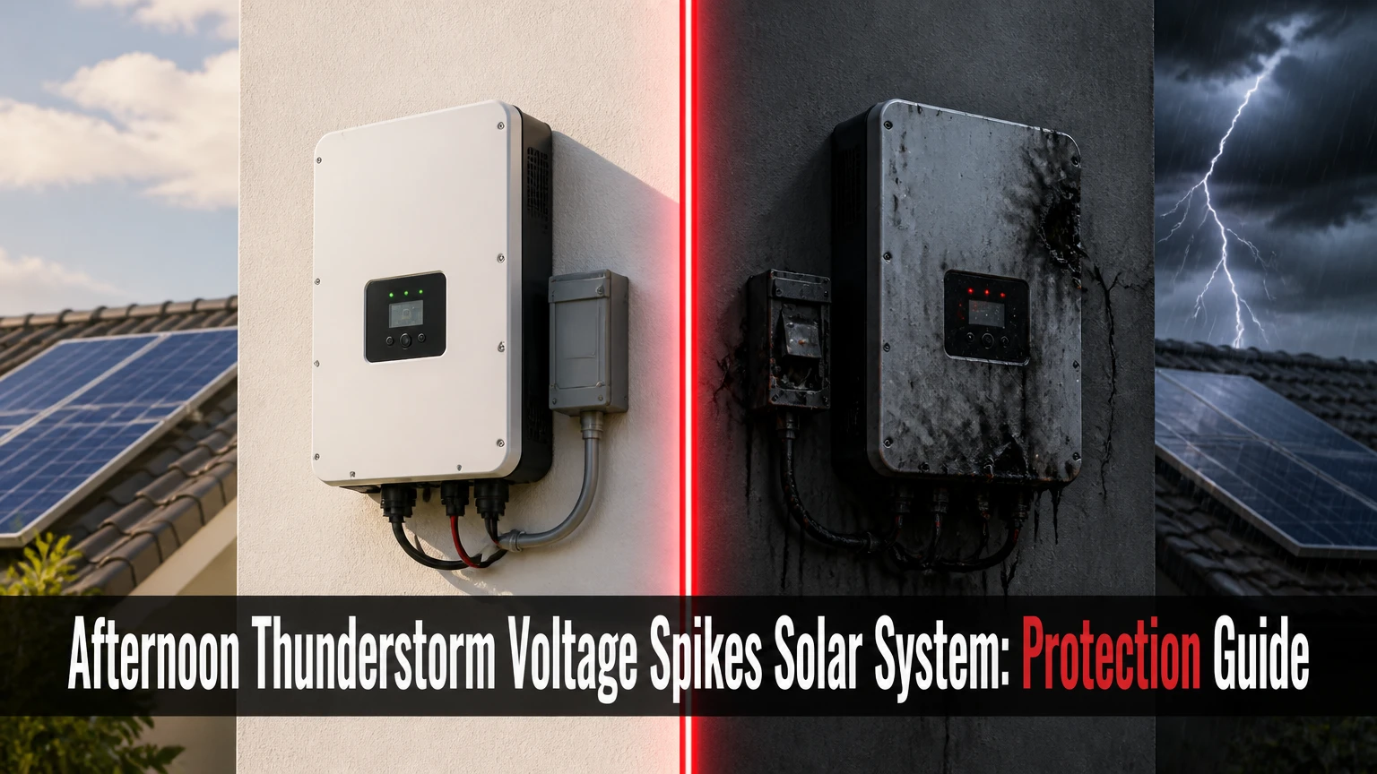
An afternoon thunderstorm voltage spike in a solar system is a short transient overvoltage caused by nearby lightning, a direct strike, or utility switching. The surge can enter through PV conductors, AC wiring, grounding and bonding paths, or communications cables, so effective protection requires coordinated SPDs, sound bonding, short conductors, and a compliant lightning protection design.
Key Facts at a Glance
A nearby lightning strike can induce a damaging transient without touching the solar array.
PV protection normally requires attention to both the DC array circuit and the inverter’s AC circuit.
A Type 2 PV SPD is commonly used for induced surges, while Type 1 or combined Type 1+2 devices may be required where a lightning protection system or direct-strike exposure exists.
The PV SPD’s maximum continuous operating voltage, (U_c), must exceed the array’s maximum open-circuit voltage under the applicable temperature condition.
SPD connecting conductors should be as short, straight, and direct as the manufacturer and electrical code require; long loops increase clamping voltage.
A lightning rod, SPD, ground electrode, and equipment bonding network are different parts of one safety design.
What Causes Afternoon Thunderstorm Voltage Spikes in a Solar System?
Afternoon thunderstorm voltage spikes occur when lightning changes the electric and magnetic fields around a PV installation, or when a strike couples into nearby utility infrastructure. Solar panels do not create the lightning, and hot weather alone does not produce a dangerous surge; the storm’s electrical discharge and the installation’s conductor geometry determine the transient path.
The National Weather Service describes lightning as “a giant spark of electricity in the atmosphere.” That discharge produces a rapidly changing electromagnetic field. Long rooftop string cables, metal racking, inverter input conductors, and parallel communications wires can couple energy into one another.
A direct strike is the highest-energy event, but direct strikes are not the only concern. A nearby strike can induce voltage in a loop formed by positive and negative PV conductors, while a utility strike can travel toward the property on an overhead or underground service. The often-repeated 4,000-6,000 volt figure is not a universal value. Actual transient voltage depends on strike current, distance, conductor length, loop area, soil impedance, bonding, and the location of the measurement.
How does a surge reach the inverter?
A surge reaches a solar inverter through four principal routes: PV positive and negative conductors, the AC feeder, protective bonding and grounding conductors, or data cables such as Ethernet, RS-485, rapid-shutdown wiring, and battery communications. The inverter becomes vulnerable when those routes have different transient potentials.
| Entry route | Typical coupled equipment | Common damage pattern | First inspection point |
|---|---|---|---|
| PV DC conductors | String fuses, MPPT inputs, DC SPD | Ground fault, failed MPPT, insulation alarm | Combiner and inverter DC terminals |
| AC service conductors | Main panel, inverter output stage | AC overvoltage, relay failure, breaker trip | Service panel and AC SPD |
| Bonding paths | Racking, module frames, inverter chassis | Punctured insulation, carbon tracks, nuisance faults | Bonding jumpers and lugs |
| Communications cables | Gateway, optimizer, battery controller | Lost monitoring, damaged network port | Surge protection and cable shield entry |
The highest transient voltage does not always appear at the lightning strike location. A poorly bonded array can develop a large potential difference between its frame and the inverter chassis, forcing current through insulation, cable shields, or semiconductor devices.
What Is the Difference Between a Direct Strike and an Induced Surge?
A direct lightning strike physically attaches to the array, structure, or nearby service and introduces extreme current into the installation. An induced surge occurs when a nearby discharge or utility event creates a changing electromagnetic field or conducted transient, coupling energy into PV or AC wiring without a panel receiving the bolt.
| Event type | Physical coupling | Relative energy | Likely consequence | Main control |
|---|---|---|---|---|
| Direct array strike | Attachment to panel, frame, or cable | Very high, potentially tens of kiloamperes | Fire, arc damage, destroyed modules and inverter | Engineered LPS, separation, bonding, SPDs |
| Nearby lightning | Electromagnetic induction | High but installation-dependent | SPD operation, MPPT or control-board damage | Short cable loops, coordinated SPDs |
| Utility lightning | Conducted through service | Moderate to high | AC stage and household electronics failure | Service-panel SPD and AC bonding |
| Utility switching | Conducted transient | Usually lower | Inverter reset, nuisance trips, premature SPD wear | AC SPD and utility assessment |
A Type 2 SPD can reduce many induced and switching transients, but it is not a promise that an inverter will survive a direct strike. Lightning protection standards treat interception, down-conductors, separation distance, equipotential bonding, and surge protection as coordinated design elements.
Which SPD Does a Solar PV System Need?
Most grid-connected PV systems need protection on the DC and AC sides, with the exact SPD type determined by the risk assessment, service arrangement, inverter design, and local code. Type 2 devices commonly address induced surges, while Type 1 or Type 1+2 devices may be appropriate at a service entrance or where an external lightning protection system can conduct partial lightning current.
Type 3 devices have lower discharge capability and are normally installed close to sensitive loads. A Type 3 protector is not a substitute for a properly rated PV DC SPD at a string combiner or inverter input.
| SPD category | Typical installation point | Main technology | Appropriate use |
|---|---|---|---|
| Type 1 | Service entrance or lightning-current boundary | Spark gap or hybrid design | Partial direct-lightning current where required |
| Type 2 | PV combiner, inverter DC input, AC panel | MOV or hybrid module | Induced lightning and switching surges |
| Type 3 | Near sensitive electronic load | Low-energy point-of-use protection | Final-stage equipment protection |
| Type 1+2 | Main distribution or dedicated PV enclosure | Combined spark gap and MOV | Installations needing coordinated upstream and downstream protection |
How do you read a PV SPD nameplate?
Choose a PV SPD by matching its DC operating voltage, protection level, discharge-current ratings, pole configuration, short-circuit withstand, and backup protection to the actual array and inverter. A device labeled “solar” is not automatically suitable for every string voltage or grounded and floating PV topology.
| Rating | Meaning | Practical selection rule | Typical residential consideration |
|---|---|---|---|
| (U_c) | Maximum continuous operating voltage | Exceed the cold-weather maximum PV (V_{oc}) | 600, 800, or 1,000 V DC system class |
| (U_p) | Voltage protection level | Keep below equipment impulse withstand after coordination | Common device values near 2.0-3.8 kV |
| (I_n) | Nominal discharge current | Higher rating supports repeated standard impulses | 10-20 kA commonly encountered |
| (I_{max}) | Maximum discharge current | Compare with exposure and manufacturer design | 20-40 kA common; higher values exist |
| SCCR | Short-circuit current rating | Meet or exceed available PV fault current | Verify with inverter and fuse schedule |
| Poles and mode | Protected conductors and connection mode | Match positive, negative, and protective-earth arrangement | 2-pole or 3-pole PV configurations |
The AI Overview’s suggestion that (U_p) should always be below 2.2-2.5 kV is too narrow. PV SPDs have different test classes and protection levels, and the correct value depends on the inverter’s impulse withstand rating, conductor inductance, coordination, and applicable IEC or UL requirements.
Should the AC and DC Sides Both Have Surge Protection?
Yes, a typical grid-connected solar installation should evaluate both sides because a DC-only SPD leaves the inverter’s AC output and utility connection exposed. A matched AC SPD at the distribution equipment and a correctly rated PV SPD near the inverter or combiner reduce the number of unprotected entry routes.
Protection may also be needed for battery DC circuits, generator inputs, monitoring cables, and external Ethernet links. Microinverter systems distribute electronics across the roof, so the installer must evaluate branch circuits and trunk cables rather than assuming the central inverter strategy applies unchanged.
What does coordinated protection look like?
A coordinated design places the appropriate SPD at the service entrance, PV array boundary, inverter terminals, and sensitive downstream circuits, while keeping the protective path low impedance. Coordination means the upstream device can discharge larger energy and the downstream device can clamp the residual voltage without causing unnecessary interaction.
| System architecture | DC protection location | AC protection location | Additional concern |
|---|---|---|---|
| String inverter | Combiner and inverter DC input | Main panel or inverter AC disconnect | Long rooftop strings |
| Microinverters | Array trunk or equipment boundary | Branch circuit and service panel | Many roof-level electronics |
| Hybrid inverter | PV input and battery terminals | Load panel and service entrance | Battery and backup circuits |
| Off-grid inverter | PV combiner and inverter input | Generator and load distribution | No utility path, but generator transients |
An SPD cannot remove surge energy from the electrical system. It diverts current through a designed path and limits the voltage difference that equipment experiences. That distinction explains why an SPD with a very fast response time can still perform poorly when its connecting wires are long.
Does Grounding Prevent Solar Inverter Damage?
Grounding alone does not prevent solar inverter damage, and a low earth-resistance measurement does not prove that a lightning current path is safe. Effective protection requires equipment grounding, equipotential bonding, an appropriately designed grounding electrode system, correct SPD connections, and, where needed, a lightning protection system designed under the applicable standard.
The AI Overview’s recommendation to keep earth resistance below 5 or 10 ohms is not a universal lightning rule. Soil resistivity, electrode geometry, bonding, touch-voltage control, and the standard used by the jurisdiction matter more than one isolated resistance number. NFPA 780 and IEC 62305 address complete protection systems, not a single magic resistance threshold.
A separate earth pit for a lightning rod can increase dangerous voltage differences if it is not bonded to the building’s grounding and bonding system. Lightning protection conductors and power-system grounding may have distinct routing requirements, but they cannot be treated as electrically unrelated islands. A qualified designer must follow local code and the required separation or bonding strategy.
What bonding details matter most?
Bond module frames, racking, inverter enclosures, cable trays, and lightning protection components according to the listed equipment and local code. Use corrosion-compatible lugs, protect outdoor connections from moisture, and avoid sharp bends or narrow conductors in high-frequency surge paths.
The common recommendation to use a fixed 6 AWG or 4 AWG copper conductor for every lightning path is also oversimplified. Conductor size, material, routing, mechanical protection, and the governing standard determine suitability. The installer should not replace a specified conductor with a smaller equipment grounding conductor merely because a continuity test passes.
How Should an Installer Reduce Surge Exposure?
An installer should first assess lightning exposure and conductor routes, then create short, straight SPD connections, bond metallic parts, protect both electrical directions, and verify the completed installation against the inverter and SPD instructions. The work normally requires a licensed electrician or qualified solar professional because PV circuits can remain energized in daylight.
Step 1: Document the system
Record the inverter model, maximum DC voltage, array (V_{oc}), string count, conductor lengths, service type, battery equipment, communications cables, and existing SPDs. Check whether the property has an external lightning protection system, overhead utility service, exposed ridge location, or frequent storm activity.
Checkpoint: The design file identifies every conductor entering the inverter area.
Common mistake: Selecting an SPD from the nominal inverter label without calculating cold-weather PV (V_{oc}).
Step 2: Inspect the protection boundary
Find the DC combiner, inverter disconnect, AC panel, service entrance, battery cabinet, generator connection, and data-cable entry. Determine whether each path has a listed SPD with a visible status indicator and a suitable backup fuse or breaker.
Checkpoint: The installer can trace every surge path from array and utility to earth and equipment bonding.
Common mistake: Protecting the PV strings while leaving the AC panel or battery circuit unprotected.
Step 3: Install or replace coordinated SPDs
Use devices listed for the jurisdiction, such as products evaluated to relevant UL 1449 requirements in the United States or IEC 61643-31 for PV applications where applicable. Match (U_c), (U_p), discharge current, poles, grounding arrangement, and SCCR.
Checkpoint: The SPD documentation matches the measured system voltage and wiring topology.
Common mistake: Installing an AC SPD on a PV DC circuit because the voltage label appears similar.
Step 4: Minimize conductor inductance
Route SPD conductors directly, with minimal bends and no unnecessary loops. The often-cited 50 cm maximum is a useful field target, but the total connection path, conductor arrangement, manufacturer instructions, and code govern the final installation.
Checkpoint: The conductors are short, separated as required, mechanically secure, and visibly free of coils.
Common mistake: Mounting the SPD beside the inverter while routing its earth lead around the enclosure.
Step 5: Verify bonding and mechanical safety
Check frame bonds, racking jumpers, inverter equipment grounding, cable-tray continuity, corrosion, enclosure ratings, and lightning protection separation or bonding. Do not disconnect grounding conductors to troubleshoot nuisance faults.
Checkpoint: Continuity and torque checks agree with the installation documentation.
Common mistake: Driving an isolated ground rod and assuming the rod replaces bonding to the building system.
Step 6: Test and document
A qualified person should test polarity, insulation resistance where appropriate, disconnect operation, SPD status, grounding continuity, and inverter startup according to the equipment manual. Photograph the completed wiring and record SPD model numbers and replacement dates.
Checkpoint: The inverter starts without isolation or ground-fault alarms, and all protection indicators show serviceable status.
Common mistake: Energizing the system immediately after replacing an SPD without checking why the original failed.
How Much Does Solar Surge Protection Cost?
Typical US residential equipment and labor costs range from about $200 for a single AC or DC SPD installation to $5,000 or more for engineered lightning interception, extensive bonding, and difficult roof access. Local labor rates, trenching, panel upgrades, roof height, and permit requirements can change the total substantially.
| Work item | Typical equipment cost | Typical labor cost | Typical duration |
|---|---|---|---|
| Type 2 PV DC SPD | $50-$180 | $150-$400 | 1-3 hours |
| Type 2 AC panel SPD | $60-$200 | $150-$350 | 1-2 hours |
| Combined DC and AC protection | $150-$500 | $300-$900 | 3-6 hours |
| Bonding or grounding correction | $100-$800 | $300-$1,500 | 3-10 hours |
| Engineered external LPS | $1,500-$5,000 equipment | $1,000-$4,000 labor | 1-3 days |
These figures are planning ranges, not quotations. A replacement SPD cartridge may cost $30-$150, while a damaged inverter can cost $1,000-$5,000 for equipment and labor, excluding lost production and warranty exclusions.
Which Protection Strategy Fits Each Solar Installation?
The appropriate strategy depends on strike exposure, array location, inverter architecture, utility arrangement, and the cost of downtime. Type 2 AC and DC protection is often proportionate for a suburban array without a structural LPS, while a ridge-top or isolated property may justify a formal risk assessment and engineered lightning interception.
| Installation situation | Minimum design discussion | Stronger option | Main limitation |
|---|---|---|---|
| Suburban rooftop | AC and DC Type 2 SPDs | Service entrance Type 1+2 SPD | Does not guarantee direct-strike survival |
| Ridge-top rural home | IEC 62305 or NFPA 780 assessment | External LPS plus coordinated SPDs | Higher design and roof cost |
| Ground-mounted array | DC boundary protection and bonding | Buried metallic pathways with engineered LPS | Long trench conductors can couple surges |
| Off-grid cabin | PV, battery, generator, and data protection | Enclosed, replaceable SPD assemblies | Replacement access may be difficult |
| Microinverter array | AC branch and service protection | Roof-level equipment protection | More electronic devices are exposed |
Structural lightning protection is not automatically beneficial when air terminals are added casually beside panels. Air-terminal placement, down-conductor routing, separation distance, bonding, and roof penetrations require a coherent design. A rod installed without a low-impedance current path can redirect rather than eliminate risk.
Why Did the Inverter Fail After an Afternoon Storm?
An inverter that fails after an afternoon storm may have received a conducted surge, an induced transient, a ground-potential rise, or a secondary failure from a spent SPD. The failure does not prove that lightning struck the panels, because AC service wiring, communications cables, and bonding paths can deliver damaging energy independently.
| Symptom after storm | Probable area | Safe diagnostic action | Likely repair scope |
|---|---|---|---|
| DC overvoltage alarm | PV input or SPD | Photograph code, isolate only as instructed | SPD, fuse, MPPT, or wiring |
| Isolation fault | Module, cable, connector | Stop repeated resets | Insulation and connector testing |
| No display or communications | Control board or data path | Check AC and DC status indicators | Gateway, board, or network protection |
| Breaker trips repeatedly | AC stage or wiring | Leave circuit isolated | Electrician fault diagnosis |
| SPD indicator red | SPD cartridge depleted | De-energize before replacement | Cartridge and cause investigation |
Do not repeatedly reset an inverter that smells burned, shows melted plastic, has a red SPD window, or trips a breaker. Disconnecting PV strings can be hazardous because sunlight maintains DC voltage, and internal capacitors may retain energy after shutdown.
What Maintenance Should Follow a Storm?
After a nearby lightning storm, inspect the inverter display, SPD indicators, enclosure condition, monitoring data, and production history, but do not open energized equipment. A qualified technician should investigate any red SPD indicator, ground-fault code, isolation alarm, burning odor, unexplained production loss, or repeated shutdown.
The green status window on many modular SPDs indicates an available protective element, while red commonly indicates disconnection or end of life. Indicator colors differ by manufacturer, so the product manual controls. A green window also cannot prove that the SPD clamped a previous surge successfully or that the rest of the grounding system is intact.
What should homeowners check safely?
- View the equipment from outside without removing covers.
- Record inverter alarms, time, weather, and production loss.
- Photograph SPD status windows and visible damage.
- Keep failed equipment isolated if the manufacturer permits.
- Contact the installer, utility, insurer, and equipment manufacturer when appropriate.
- Do not touch wet enclosures, exposed conductors, or damaged rooftop equipment.
Storm insurance claims benefit from dated photographs, monitoring records, electrician reports, and the failed SPD cartridge. Warranty coverage varies because some manufacturers exclude lightning and other external electrical events.
What Are the Most Common Solar Surge Protection Mistakes?
The most damaging design mistakes involve incomplete protection paths, excessive conductor length, incorrect voltage selection, and unsafe assumptions about grounding. Field inspections frequently find protection installed at the inverter while the cable route, service entrance, battery, or communications path remains electrically exposed.
- Using (U_c) below cold-weather (V_{oc}): The SPD can conduct during normal operation or fail prematurely. Calculate the array’s maximum voltage at the site’s minimum design temperature.
- Protecting DC but not AC: A utility-side surge can enter through the inverter output and damage relays, filters, or control electronics.
- Creating long SPD loops: Inductance adds voltage during a fast pulse, reducing the benefit of a low nameplate (U_p).
- Installing an isolated lightning ground: A separate rod can develop a dangerous potential difference unless the complete design addresses bonding.
- Ignoring data cables: Ethernet, RS-485, and battery communication wires can bypass electrical SPDs.
- Replacing only the cartridge: A failed SPD may indicate a severe event, poor bonding, wrong rating, or repeated utility disturbance.
A practical rule is to inspect the whole surge current path, not merely the protector’s green window. The SPD is one component in a circuit that includes conductors, disconnects, enclosures, bonds, and the earth interface.
What Does the AI Overview Get Wrong or Oversimplify?
The AI Overview correctly identifies direct strikes, nearby induced surges, DC and AC protection, SPD status indicators, and conductor length as important topics. Several numerical and installation claims require qualification before a homeowner uses them as design instructions.
First, lightning current is not automatically “injected into the framework” at 100,000 amperes. Lightning currents vary widely, and a direct attachment point, current division, bonding, and structure determine what the PV frame carries. Second, a Type 1 SPD is not a guarantee against a direct array strike; direct attachment can damage modules, glass, racking, wiring, and the building even when SPDs operate correctly.
Third, the claim that Type 2 devices protect against 90 percent of indirect surges lacks a dependable universal basis. Performance depends on exposure, location, coordination, and installation quality. Fourth, a lightning protection ground should not be casually described as completely independent from the building grounding system. Equipotential bonding and code-compliant design control that relationship.
Finally, no SPD can “bleed off” lightning harmlessly into earth in the simplistic sense. SPDs limit voltage by conducting surge current, and the current still creates electromagnetic fields, voltage rise, thermal stress, and possible equipment damage.
Frequently Asked Questions
Can solar panels attract lightning during an afternoon storm?
Solar panels do not attract lightning simply because they generate electricity. Panels can provide conductive metal and elevated surfaces, so an array may become part of a strike path if lightning attaches to the building or nearby structure. Site exposure, height, terrain, wiring, and structural protection determine risk more than solar generation itself.
Should I turn off my solar system before a thunderstorm?
Do not climb onto a roof or handle outdoor PV disconnects solely because a storm is approaching. A homeowner can follow the inverter manufacturer’s approved shutdown procedure from a safe location, but shutdown does not remove lightning risk because modules remain exposed and some circuits may remain energized.
Can a surge protector stop a lightning strike?
A surge protector can limit transient voltage and divert part of the surge current, but it cannot stop or guarantee survival against a direct lightning strike. A complete design combines SPDs with bonding, suitable conductors, separation, and an engineered lightning protection system where the site risk warrants it.
How long do solar SPDs last?
Solar SPDs have no guaranteed calendar life because service life depends on the number and magnitude of surges, utility conditions, temperature, and device quality. A modular SPD may fail after one severe event or operate for many years. Replace it when its indicator shows end of life or testing identifies damage.
Are battery systems more vulnerable to thunderstorm surges?
Battery systems add DC conductors, a battery management system, communications wiring, and backup load circuits that can provide additional surge paths. Hybrid inverter installations therefore require protection review on PV, battery, grid, generator, load-panel, and data interfaces rather than relying on the PV SPD alone.
The Bottom Line
Afternoon thunderstorm voltage spikes in a solar system can enter through PV strings, AC service wiring, bonding paths, and communications cables, whether or not lightning touches the array. The defensible protection strategy is a site-specific, code-compliant combination of correctly rated DC and AC SPDs, short connection paths, continuous bonding, appropriate grounding, and engineered structural lightning protection for high-exposure properties.