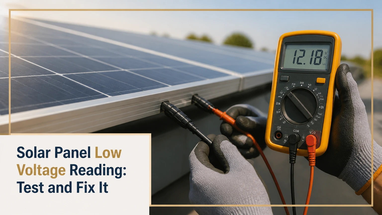
A solar panel low voltage reading means measured panel voltage is materially below the module’s rated open-circuit voltage, or the system voltage falls below the controller or inverter’s expected operating range. The correct diagnosis depends on whether the measurement is Voc, Vmp, string voltage, or controller input voltage, because each reading has a different normal value and failure pattern.
Key Facts at a Glance
- A module’s Voc is measured with the panel disconnected from every load; Vmp is measured while the panel is delivering power.
- A typical crystalline-silicon module has a Voc around 37-50 volts and an operating voltage around 30-42 volts, but the nameplate is the controlling reference.
- Solar-module voltage usually falls as cell temperature rises, commonly by about 0.25%-0.40% per °C above the 25°C test condition.
- A normal Voc that collapses when current flows usually indicates resistance in a connector, cable, fuse, isolator, or terminal rather than a weak module.
- A zero-volt result can come from reversed probing, an open circuit, a disconnected connector, or a shorted bypass diode; it does not prove that the panel itself is dead.
- Never unplug MC4 connectors under load. Photovoltaic DC arcs can persist, damage equipment, and cause severe burns.
What Does a Solar Panel Low Voltage Reading Mean?
A solar panel low voltage reading is a diagnostic result, not a complete fault description. The reading must be compared with the correct nameplate value under similar conditions: Voc against Voc, Vmp against Vmp, and string voltage against the expected number of panels in series.
Solar panels contain photovoltaic cells connected mainly in series. Series-connected cells add voltage, while parallel paths add current. Sunlight intensity has a much larger immediate effect on current than on voltage, so a cloudy panel may still show a substantial fraction of its rated voltage while producing very little usable power.
The National Renewable Energy Laboratory defines photovoltaics as “the direct conversion of light into electricity.” That distinction matters during testing: a voltmeter measures electrical potential without proving that the module can deliver current. A defective panel can therefore show a plausible voltage with almost no load capacity.
What Voltage Should a Solar Panel Produce?
A solar panel should produce a Voc close to its datasheet value in bright, unshaded conditions, while Vmp is normally lower because the module is supplying current. A “12-volt” battery panel, for example, may have a Vmp near 18 volts and a Voc near 22 volts.
| Module label or system type | Typical Voc | Typical Vmp | Correct comparison |
|---|---|---|---|
| 12 V nominal battery module | 20-24 V | 17-20 V | Compare isolated panel Voc with nameplate Voc |
| 60-cell residential module | 37-42 V | 30-35 V | Compare module voltage at the same temperature |
| 72-cell residential module | 45-50 V | 36-42 V | Check inverter minimum operating voltage |
| 100 V nominal portable module | 95-105 V | 75-85 V | Use a meter rated above maximum possible DC voltage |
Nominal voltage is not the same as measured panel voltage. A “12-volt panel” is designed to charge a 12-volt battery through an appropriate controller; it does not normally measure 12 volts at open circuit.
Why Is the Solar Panel Voltage Low?
Low solar panel voltage usually results from heat, weak irradiance, shading, an electrical connection problem, a damaged bypass diode, or a mismatch between the measured point and the expected specification. The fastest separation is to compare isolated Voc with loaded voltage at the same panel.
Temperature and Sunlight
Temperature lowers voltage predictably. If a module has a Voc of 49.5 volts at 25°C and a temperature coefficient of -0.30% per °C, a 65°C cell temperature represents 40°C above the test condition:
49.5 × [1 - (0.003 × 40)] = 43.56 V
The cell temperature can be substantially higher than outdoor air temperature. A roof module in 35°C air may have cells near 60-70°C under strong sun, depending on wind, mounting, and roof clearance.
Cloud cover reduces irradiance and current sharply, while voltage often declines less dramatically. Early morning and late afternoon readings also remain difficult to compare with a laboratory rating because irradiance, angle, and cell temperature differ.
| Condition | Typical effect on Voc | Typical effect on current | Interpretation |
|---|---|---|---|
| 25°C cell temperature, strong sun | 0% reference | 100% reference | Closest to STC rating |
| 65°C cell temperature, strong sun | 10%-14% lower | 90%-100% reference | Often normal thermal behavior |
| Bright overcast sky | 2%-10% lower | 20%-70% lower | Voltage may look acceptable while power is poor |
| Heavy shade on one module | 0%-15% lower at Voc | 50%-100% lower under load | Current loss is usually more severe |
| Snow or opaque debris | Variable, often near zero | 80%-100% lower | Remove obstruction only when safe |
These are typical field ranges, not acceptance limits. The datasheet temperature coefficient and test conditions take priority.
Shading, Soiling, and Cell Damage
A tree shadow across one cell row can activate a bypass diode. The affected module may then lose one section of its voltage under load, while an isolated meter test shows a less obvious reduction. Bird droppings, leaves, snow, and thick dust can create the same electrical symptom by blocking cell groups.
Microcracks, delamination, moisture ingress, and hot spots are more serious. Look for browned areas, bubbles, yellowed encapsulant, burn marks near the junction box, or cracked glass. Do not press on damaged glass or wash a hot module with cold water, because thermal shock can enlarge cracks.
How Do You Test a Low-Voltage Solar Panel?
Test a low-voltage solar panel by recording the system reading, isolating the module or string, measuring Voc with a properly rated DC multimeter, and then testing voltage under controlled load. The procedure normally takes 15-30 minutes for one accessible module, excluding rooftop access and shutdown coordination.
Before You Start
| Requirement | Typical value or specification | Why it matters |
|---|---|---|
| Digital multimeter | CAT III or CAT IV, DC range above system maximum | Prevents meter damage and arc risk |
| Voltage range | At least 1.25 times expected maximum | Provides measurement margin |
| Test condition | Clear or bright sky, preferably 9 a.m.-3 p.m. | Improves comparison quality |
| Required PPE | Insulated gloves, eye protection, nonconductive footwear | Reduces shock and arc injury risk |
| Reference data | Module Voc, Vmp, coefficient, string count | Defines the expected result |
A photovoltaic array can remain energized whenever light reaches it. Turn off the inverter or controller according to its shutdown procedure, open the designated DC isolator, and verify the manufacturer’s instructions before disconnecting any connector. Roof work should be handled by a qualified solar technician.
Step 1: Record the Original Reading
Write down the exact voltage, current if available, equipment display, time, weather, battery state of charge, and whether the reading came from a module, string, controller, or inverter. A controller showing 14.2 volts is usually displaying battery charging voltage, not panel Voc.
Success checkpoint: You can identify the measurement point and its expected voltage range.
Common mistake: Comparing a charge-controller battery reading with the panel’s Voc label.
Step 2: Inspect the Module and Array
Check for shading, dirt, snow, standing water, cracked glass, loose cables, damaged insulation, melted connectors, and junction-box discoloration. Trace the cable from the panel to the controller or inverter, looking for sharp bends, rodent damage, unsupported cable loops, and incompatible connector brands.
Success checkpoint: No physical obstruction or heat damage remains unexplained.
Common mistake: Cleaning a module before recording the original condition and losing useful evidence.
Step 3: Measure Isolated Open-Circuit Voltage
Set the multimeter to DC voltage, choose a range above the expected array voltage, and confirm the leads are in the voltage sockets. With the module isolated and no load attached, measure across positive and negative terminals without shorting the probes.
Polarity matters. A negative display usually means the probes are reversed, not that the module produces negative voltage. Never place the meter in current mode across a panel, because that creates a short circuit and can destroy the meter or produce an arc.
Success checkpoint: The isolated reading is stable and polarity agrees with the connector markings.
Common mistake: Using a 20-volt meter on a module with a 40-volt Voc.
Step 4: Compare Voc With the Corrected Rating
Use the module’s temperature coefficient to estimate expected Voc at the current cell temperature. For a module rated at 40 volts with a -0.32% per °C coefficient, 50°C cells, 25°C above STC, predict approximately:
40 × [1 - (0.0032 × 25)] = 36.8 V
A field Voc within roughly 5%-10% of a temperature-corrected expectation often warrants further load testing rather than immediate replacement. This is a practical screening range, not a universal manufacturer warranty threshold.
Success checkpoint: The difference is explained by temperature, irradiance, or a documented electrical condition.
Common mistake: Expecting the nameplate Voc on a hot roof at noon.
Step 5: Test the Circuit Under Load
Reconnect the system only through the approved shutdown and startup sequence. Measure voltage at the panel, then at the controller or inverter input while the array is producing current. A large difference between those locations indicates cable, connector, fuse, isolator, or terminal resistance.
Use the voltage-drop relationship:
Voltage drop = current × total circuit resistance
For a 10-amp circuit with 0.20 ohms of total resistance, the loss is 2 volts. On a 36-volt operating circuit, that is about 5.6%, enough to reduce output and create connector heating.
Success checkpoint: Panel-side and controller-side loaded readings are close to the designed cable-loss limit.
Common mistake: Measuring resistance on an energized circuit or relying on an ohms reading through connected electronics.
What Does Each Low-Voltage Reading Mean?
The numerical pattern narrows the fault, but no single voltage value proves a specific component failure. Module cell count, bypass-diode arrangement, irradiance, temperature, and the test location all change the interpretation.
| Measured pattern | Most likely causes | Confirming test | Typical response |
|---|---|---|---|
| 0 V at isolated panel | Open cable, wrong terminals, failed junction connection, shorted diode | Polarity check and junction-box diagnosis | Repair only if accessible and approved |
| Negative voltage | Reversed probes or reversed connector polarity | Reverse probes and trace polarity | Correct polarity before reconnection |
| 10%-15% below adjusted Voc | Heat, weak sun, aging, meter error | Repeat under brighter conditions | Monitor if loaded output is normal |
| About one-third lower | Bypassed cell section or module-specific diode fault | Compare with identical modules | Isolate, inspect, or replace |
| About one-half lower | Bypass path active in a two-section design | Compare section behavior and current | Qualified diode or module repair |
| Normal Voc, low loaded voltage | Resistance, failing cable, fuse, isolator, or controller input issue | Measure both ends under load | Repair connection or component |
| Normal panel voltage, low battery charge | Controller setting, battery fault, shading, or insufficient current | Check battery, controller mode, and current | Diagnose the charging system |
Bypass Diode Diagnosis
A bypass diode protects shaded cell groups by providing a current path around them. A shorted diode can permanently remove one cell section from the voltage, while an open diode may fail to protect cells during shading.
A reading near one-half or one-third of rated Voc can indicate a bypass-diode problem, but the fraction depends on the panel’s number of cell substrings and diode layout. Many modern modules use three bypass diodes, while some small modules use fewer. Treat the pattern as a clue, not a verdict.
Do not open a sealed junction box on a roof without confirming that the module warranty permits it. Diode-mode measurements made while the panel remains connected to cells, cables, or other diodes can be misleading. Replacement diodes must match reverse-voltage, forward-current, temperature, and package requirements.
How Much Voltage Drop Is Acceptable in Solar Wiring?
A practical design target is usually no more than 2%-3% voltage drop on a critical DC run, although a manufacturer or system designer may permit a higher total loss. The allowable value depends on array voltage, cable length, current, controller start voltage, and whether the circuit is a short battery connection or a long PV run.
| Circuit example | One-way length | Current | Typical cable | Approximate drop |
|---|---|---|---|---|
| 12 V battery connection | 5 ft | 20 A | 6 AWG copper | 0.10-0.15 V |
| 12 V PV-to-controller run | 30 ft | 10 A | 10 AWG copper | 0.60-0.75 V |
| 36 V module string | 50 ft | 10 A | 10 AWG copper | 1.0-1.3 V |
| 400 V rooftop string | 100 ft | 10 A | 10 AWG copper | 2.0-2.6 V |
The last example may represent less than 1% of circuit voltage, while the second example represents roughly 2%. The same cable loss has a different system consequence at different voltages.
Connector resistance deserves special attention. A partially seated or poorly crimped MC4 connector can pass a no-load voltage test and then heat under current. Discoloration, softened plastic, a sharp temperature difference between paired connectors, or an odor of overheated plastic warrants immediate shutdown by a qualified person.
Should You Use MPPT or PWM?
MPPT is usually the better controller for a higher-voltage array, long cable run, cold-weather series string, or system where available solar energy matters. PWM can be appropriate for a small, short-run battery system when the panel’s operating voltage is intentionally matched to the battery.
| Criterion | MPPT controller | PWM controller |
|---|---|---|
| Panel-to-battery voltage | Converts higher PV voltage to battery voltage | Pulls panel voltage near battery voltage |
| Typical conversion efficiency | About 94%-99% for quality units | Often 65%-85% system utilization, depending on match |
| Series-string compatibility | Commonly supported within input limits | Usually unsuitable for high-voltage strings |
| Best cable strategy | Higher PV voltage reduces current and cable loss | Requires lower-voltage, higher-current wiring |
| Typical cost | $80-$350 or more | $20-$80 |
| Main limitation | Higher price and strict maximum-voltage limit | Wastes panel voltage when Vmp exceeds battery needs |
MPPT cannot repair a weak panel, corroded connector, shaded array, or undersized cable. It can recover energy that a compatible high-voltage panel would otherwise lose through PWM control, but it does not create missing Voc.
Check cold-weather Voc before configuring a series array. Voc rises as temperature falls, and the coldest design temperature can push a controller beyond its absolute input limit even when a hot-weather measurement appears safe.
Why Is a New Installation Showing Low Voltage?
A new installation showing low voltage most often has a wiring, configuration, polarity, connector, or specification error rather than age-related module degradation. Compare each string’s panel count, polarity, Voc, and cable route with the commissioning record before changing components.
| New-installation fault | Field symptom | Verification | Corrective action |
|---|---|---|---|
| One string wired short | String reads one module section low | Count series modules and measure polarity | Rewire under approved shutdown |
| Wrong connector pair | Zero or unstable voltage | Check connector engagement and polarity | Replace incompatible connector set |
| PWM used with high-voltage panel | Battery charges slowly | Compare panel Vmp with battery voltage | Use a correctly sized MPPT controller |
| Inverter below startup voltage | No production early in day | Compare string voltage with inverter minimum | Reconfigure strings or equipment |
| Shading overlooked in design | Output falls at a predictable time | Record shade pattern and string current | Mitigate shade or redesign |
| Incorrect controller setting | Voltage appears normal, charging does not | Check battery chemistry and charge profile | Correct settings or controller |
A commissioning test should record open-circuit voltage, operating current, insulation resistance where required, polarity, and inverter startup behavior. If the installer cannot provide those records, request a documented retest rather than accepting a verbal claim that the voltage is normal.
What If the Voltage Suddenly Dropped on an Older System?
A sudden voltage drop on an older system points toward a failed connector, blown fuse, cable fault, water ingress, bypass diode, isolator, or inverter input problem. Gradual loss across all modules is more consistent with soiling, seasonal irradiance, degradation, or a monitoring change.
Compare today’s reading with historical production and with neighboring strings. One low string suggests a local fault; every string being low suggests weather, a common disconnect, controller behavior, or an inaccurate measurement.
Residential Rooftop Arrays
String inverters can expose a weak string through low input voltage or reduced power. Microinverters and power optimizers limit the effect of one module on other modules, but they add electronics, communications, and replacement complexity.
A rooftop owner should not open module junction boxes or unplug connectors while sunlight is present. Provide the technician with the string number, time of failure, inverter code, weather conditions, and photographs taken from ground level.
RV and Off-Grid Systems
Battery voltage can confuse diagnosis. A controller may show 13.8 volts at its battery terminals while the panel produces 18-22 volts at its own terminals. Measure both points, then record charging current and battery state of charge.
A long 12-volt cable run can lose a meaningful percentage of voltage. Raising PV voltage with a series configuration and using an MPPT controller can reduce cable current, but the controller must support the resulting cold-weather Voc.
Can You Repair the Panel or Should You Replace It?
Replace a module when glass, laminate, internal cell connections, or a sealed junction box has failed and the repair would compromise safety or warranty. A qualified technician may repair an accessible connector, external cable, fuse, or replaceable diode when the module manufacturer permits the work.
| Fault location | Repair suitability | Typical parts cost | Typical labor time |
|---|---|---|---|
| External MC4 connector | Usually repairable | $5-$20 per pair | 15-30 minutes |
| PV cable or terminal | Usually repairable | $10-$80 | 30-120 minutes |
| String fuse or isolator | Usually repairable | $10-$100 | 30-90 minutes |
| Accessible bypass diode | Sometimes repairable | $3-$15 | 30-90 minutes |
| Cracked glass or delamination | Generally replace module | $100-$400 per module | 1-3 hours |
| Internal cell interconnect | Usually replace module | $100-$400 per module | 1-3 hours |
Typical costs vary by country, roof access, labor rates, tax, shipping, and module availability. In Bangladesh, small connector or diode parts may cost roughly Tk 300-Tk 1,500, while controller replacements may range from Tk 2,000 for basic PWM equipment to Tk 35,000 or more for higher-current MPPT equipment. Confirm local pricing before budgeting.
Common Mistakes That Produce False Diagnoses
- Comparing Voc with Vmp. A panel operating at its maximum-power point should read below its open-circuit rating.
- Testing in current mode. A multimeter set to amps can short the panel when placed across its terminals.
- Ignoring temperature. Hot cells naturally produce lower voltage than the 25°C standard test condition.
- Calling every half-voltage result a diode failure. Cell-substring layouts differ, and a half-reading can also result from wiring or measurement location.
- Using resistance testing on live PV equipment. Ohms measurements require a de-energized circuit and disconnected electronics.
- Replacing the controller first. A controller cannot compensate for a high-resistance connector, open string, or damaged module.
- Mixing panel specifications in one series string. The lowest-current module can constrain the operating current of the entire string.
- Spraying contact cleaner into sealed MC4 connectors. Use connectors and procedures approved for PV applications; contamination or poor sealing can worsen the fault.
A particularly counterintuitive rule is that a normal unloaded voltage does not demonstrate healthy power production. Current under load is the decisive second measurement.
When Should You Stop Testing and Call a Professional?
Stop testing when the array exceeds your meter’s rating, the roof is wet or difficult to access, connectors show heat damage, insulation is damaged, the system includes high-voltage strings, or the fault involves an inverter or battery bank. DC photovoltaic arcs can continue after AC equipment is switched off.
Escalate immediately for smoke, melted connector bodies, repeated inverter insulation faults, exposed conductors, cracked modules, or unexplained voltage between frame and conductors. A qualified electrician or solar technician can use an insulation-resistance tester, clamp meter, IV-curve tracer, thermal camera, and manufacturer service procedures.
FAQ
Does a cloudy day cause a solar panel to read zero volts?
A cloudy day usually reduces current much more than voltage, so a healthy isolated module often still shows substantial Voc. A zero-volt reading under cloud may result from severe obstruction, incorrect meter settings, reversed or disconnected leads, an open circuit, or a panel fault. Repeat the measurement in brighter conditions before replacing equipment.
Can a solar panel show voltage but produce no power?
Yes. A solar panel can show normal Voc while producing little or no power if a cell connection, cable, connector, fuse, or controller has high resistance or fails under load. Measure operating voltage and current separately. Power equals voltage multiplied by current, so voltage alone cannot establish module health.
Why does my charge controller show low solar voltage?
A charge controller may show low solar voltage because it is tracking the panel’s operating point, because the battery has pulled a PWM system near battery voltage, or because the PV input has a wiring fault. Compare controller input voltage with voltage measured at the panel under the same load and conditions.
Can a bad battery cause low solar panel voltage?
A bad battery usually causes charging or controller errors rather than lowering an isolated panel’s Voc. In a battery-coupled system, a shorted battery, incorrect charging mode, or controller protection state can alter the loaded PV reading. Test the panel independently, then test battery voltage, charging current, and controller settings.
Do solar panels lose voltage as they age?
Solar modules generally experience gradual power degradation, with voltage and current changes influenced by technology, environment, and failure mode. A sudden large voltage loss is not a normal aging pattern. Sudden failure points more strongly toward connectors, junction-box components, moisture, cracking, wiring, or electronics.
Is a 12-volt solar panel supposed to read 12 volts?
A 12-volt nominal solar panel commonly reads about 17-20 volts at Vmp and 20-24 volts at Voc. The “12-volt” label describes its intended battery-system class, not its open-circuit meter result. Always use the manufacturer’s Voc and Vmp values when evaluating a reading.
The Bottom Line
A solar panel low voltage reading should be diagnosed by identifying the measurement point, comparing the result with temperature-corrected Voc or Vmp, and separating isolated-panel voltage from loaded system voltage. Check shading and damage first, test polarity and Voc safely, then locate voltage loss across connectors, cables, fuses, controllers, and inverter inputs. Replace a module only after those tests support an internal failure.