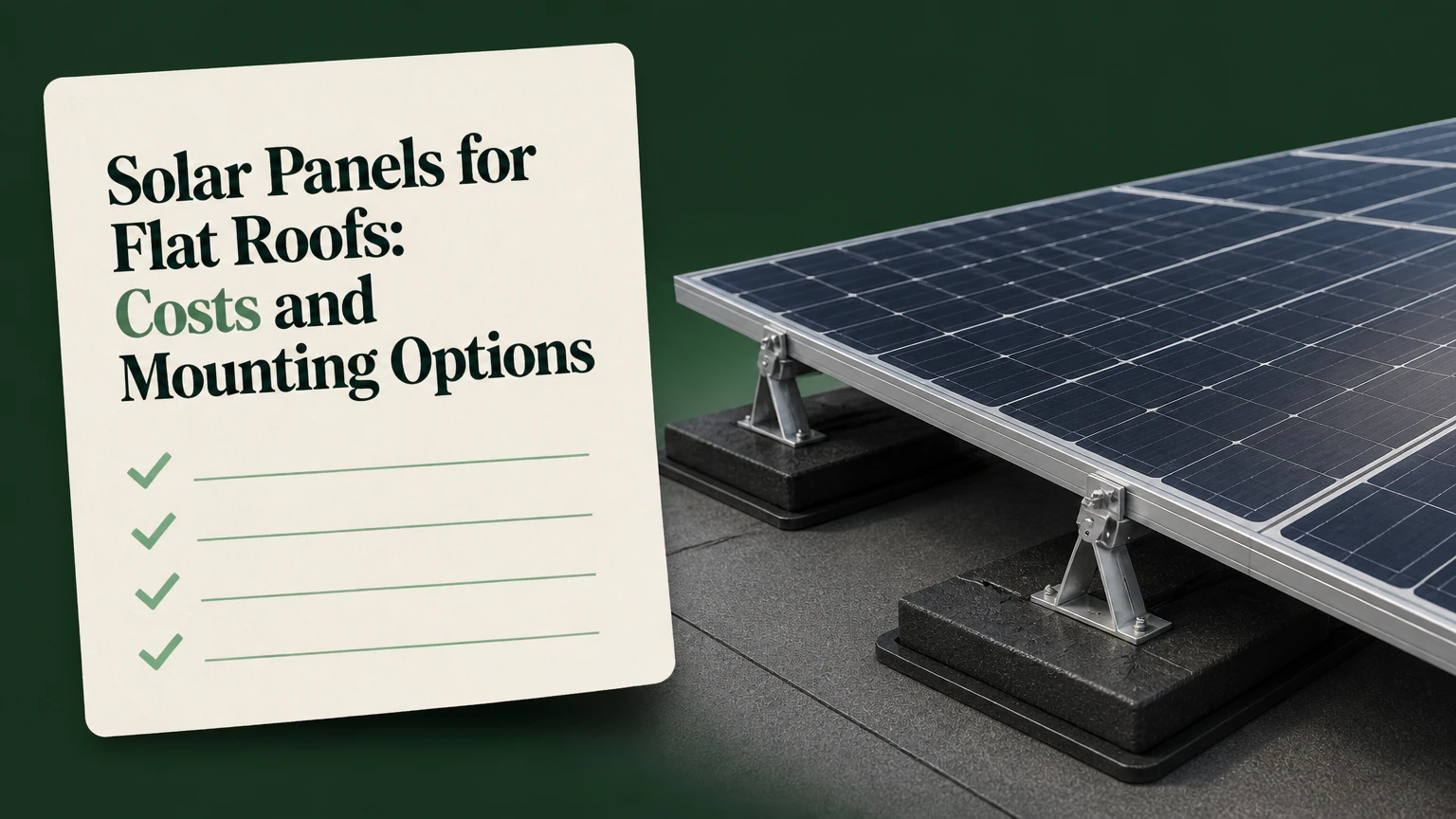
Solar panels for flat roofs use angled racking, electrical equipment, and a roof-specific attachment method to convert sunlight into usable electricity. Most systems use ballasted racks that avoid membrane penetrations, while high-wind or structurally constrained buildings may need mechanically attached rails or lightweight photovoltaic membranes.
Key Facts at a Glance
- A flat-roof solar array normally uses a 5°-15° tilt, although the engineered angle depends on latitude, shading, wind, and snow.
- Ballasted solar racks can add approximately 15-30 kilograms per square metre before local snow loads are included.
- A roof inspection should confirm membrane condition, drainage paths, structural capacity, and remaining service life before design begins.
- South-facing rows can produce strong annual output, while east-west layouts often fit more modules and spread generation across the morning and afternoon.
- A typical residential 6 kW installation costs about $15,000-$28,000 before location-specific incentives, roof repairs, and electrical upgrades.
- Solar installers must calculate wind uplift and ballast from local building-code loads rather than estimate block quantities by rule of thumb.
What Are Solar Panels for Flat Roofs?
Solar panels for flat roofs are photovoltaic modules installed above a low-slope roof on tilted supports rather than mounted flush to rafters. In building practice, a “flat” roof generally has a small drainage fall, and the solar structure must preserve that drainage while resisting wind, snow, and movement.
A standard photovoltaic module produces direct-current electricity when semiconductor cells absorb sunlight. An inverter changes that DC electricity into alternating current for building circuits, and surplus electricity may flow to a battery or the utility grid. Module-level power electronics can reduce the effect of partial shading, while string inverters can lower equipment cost on a consistent, unshaded roof.
The roof itself is part of the system design. EPDM, TPO, PVC, modified bitumen, built-up roofing, and gravel-surfaced roofs each require compatible pads, clearances, flashing details, or attachment methods. The best array is not the one with the highest panel count. It is the one that produces energy without compromising waterproofing, access, drainage, or future roof work.
How Does a Flat-Roof Solar System Work?
A flat-roof photovoltaic system works through four linked stages: sunlight becomes DC electricity, an inverter produces AC electricity, a mounting system holds the modules at a designed angle, and electrical protection connects the system to the building. The structural and drainage design determines whether the energy equipment remains safe over its service life.
Solar cells generate variable DC voltage that changes with irradiance and temperature. Maximum power point tracking, or MPPT, allows the inverter to operate the array near its best electrical output. String inverters group modules into circuits, whereas microinverters place conversion equipment behind individual modules and can improve production where roof obstructions create uneven shade.
Racking changes the panel plane from nearly horizontal to an engineered tilt. The angle affects annual energy yield, winter shading, wind exposure, snow retention, row spacing, and the amount of ballast required. A higher tilt can improve low-sun performance but usually increases wind forces and the distance between rows.
Which Tilt and Orientation Work Best?
A 10°-15° tilt is a common practical range for flat roofs, but no universal angle maximizes every project. South-facing arrays generally favor annual energy production in the Northern Hemisphere, while east-west arrays can increase roof utilization and produce a broader daily output profile.
| Design choice | Typical value | Main advantage | Main limitation |
|---|---|---|---|
| South-facing tilt | 10°-15° | Strong annual yield | Requires shading gaps between rows |
| Low south tilt | 5°-10° | Lower wind and ballast demand | More soiling and lower winter capture |
| East-west tilt | 5°-15° per side | Higher module density | Slightly lower peak annual yield in some locations |
| Steeper tilt | 20°-30° | Better low-sun exposure | More wind uplift, spacing, and ballast |
Installers model solar access with roof plans, obstruction heights, local latitude, and software such as PVsyst or HelioScope. A south-facing design is not automatically superior when parapets, HVAC units, or neighboring buildings cast shadows. On a small roof, an east-west arrangement can generate more total electricity because it sacrifices some output per module to fit additional modules.
Can a Flat Roof Support Solar Panels?
A flat roof can support solar panels only after a qualified designer verifies dead load, wind uplift, snow load, roof framing, and attachment forces. Panel weight alone is insufficient because ballast, racking, maintenance loads, accumulated snow, and local code requirements can determine the final structural demand.
A typical modern module weighs about 20-25 kilograms and covers roughly 1.8-2.2 square metres. Racking adds a smaller amount, but ballast can add approximately 15-30 kilograms per square metre for a residential system and more in exposed or high-wind locations. The actual value comes from an engineered layout.
Ask for these documents before signing:
- Roof drawings or framing plans, if available.
- A roof condition report with membrane age and repair history.
- The ballast or attachment calculation for the site’s wind and snow conditions.
- A drainage and maintenance-access layout.
- The module, inverter, racking, and fire-access specifications.
- Written confirmation of roof and solar warranty responsibilities.
The design must distinguish downward weight from uplift resistance. A roof may tolerate panel weight yet require additional attachment because wind pressure can lift the array at edges and corners. Concentrated loads also matter when ballast blocks sit over a limited number of joists or deck areas.
Which Roofs Are Suitable?
EPDM, TPO, PVC, modified bitumen, and built-up roofing can all receive solar installations when the mounting materials and detailing match the membrane. A suitable roof should have adequate remaining life, working drainage, no active leaks, and enough clear area around drains, parapets, skylights, HVAC equipment, and fire paths.
| Roof type | Common solar approach | Key inspection point | Typical concern |
|---|---|---|---|
| EPDM rubber | Ballasted pads or sealed attachments | Pad compatibility and membrane aging | Abrasion from movement |
| TPO | Ballasted trays or welded attachment details | Thermoplastic welding quality | Heat and chemical compatibility |
| PVC | Ballasted or mechanically attached rails | Manufacturer-approved interfaces | Membrane puncture and warranty |
| Modified bitumen | Ballasted or flashed penetrations | Granule loss and blistering | Heat, adhesion, and leaks |
| Built-up roofing | Engineered ballast or structural attachment | Aggregate condition and deck strength | Uneven bearing surfaces |
| Gravel-topped roof | Specialized trays or cleared zones | Gravel stability and drainage | Point loading and loose aggregate |
A roof with five years of useful life remaining is usually a poor platform for a new array with a 25-year performance horizon. Removing and reinstalling panels during reroofing can add several thousand dollars, while a planned roof replacement before solar avoids duplicated mobilization and electrical disconnection.
Flat-Roof Mounting Systems Compared
Ballasted racking is usually the preferred starting point for sound low-slope roofs because it avoids membrane penetrations, while mechanically attached racking is often better for severe wind exposure or roofs that cannot carry substantial ballast. Adhesive photovoltaic membranes solve weight and visual constraints but usually deliver lower power density and require specialized installation.
| Mounting system | Added system load | Roof penetration | Typical tilt | Best application |
|---|---|---|---|---|
| Ballasted rack | 15-30 kg/m² | None, if engineered | 5°-15° | Sound roofs with spare capacity |
| Mechanically attached rack | 5-15 kg/m² plus attachments | Yes | 5°-20° | High wind or limited ballast capacity |
| East-west ballast | 15-25 kg/m² | None, if engineered | 5°-15° | Compact roofs needing high density |
| Adhesive thin-film membrane | Under 3-5 kg/m² | None | Roof plane | Lightweight or appearance-sensitive roofs |
What Are the Advantages and Limits of Ballast?
Ballasted mounting holds panels down with concrete blocks or engineered trays placed over protective interfaces. The method reduces roof punctures and can speed installation, but its weight, wind behavior, membrane friction, and drainage clearances require detailed design.
Ballasted arrays are not automatically maintenance-free. Thermal expansion and wind vibration can move metal components against pads, so installers need compatible slip sheets or protective mats. Pads should not cover drains, trap water, or react adversely with the roof membrane. The array also needs inspection corridors wide enough for safe access and future module replacement.
When Is Penetrating Mounting Better?
Mechanically attached solar racks can be better when wind uplift is severe, ballast would exceed the roof’s capacity, or the structural framing provides reliable attachment points. Each penetration requires approved flashing or sealing, and the roofing contractor should define who owns the waterproofing warranty.
Penetrating systems do not eliminate structural engineering. They transfer forces into the deck or framing, which may require reinforcement. A mechanically attached array may weigh less than a ballasted array while producing larger local pull-out forces at individual fasteners.
How Are Solar Panels Installed on a Flat Roof?
Professional installation normally takes 2-4 on-site days for a straightforward residential system, after engineering, permits, utility review, and roof preparation are complete. The most important success factor is coordination between the solar installer, electrician, structural designer, roofing contractor, and utility.
Step 1: Inspect the Roof and Structure
Confirm membrane type, roof age, leaks, drains, parapets, roof penetrations, framing, and access routes. The installer should record roof condition with photographs before materials arrive.
Success checkpoint: The design file contains a roof plan, structural calculation, membrane approval, and drainage layout.
Common mistake: Proceeding from satellite imagery without opening roof records or inspecting concealed damage.
Step 2: Design the Array
Select module count, tilt, orientation, inverter architecture, row spacing, service clearances, and ballast or attachment locations. Keep continuous water channels open toward drains, and maintain access to HVAC equipment and roof edges.
Success checkpoint: The plan shows no blocked drains, inaccessible equipment, or shaded rows that undermine the production estimate.
Common mistake: Maximizing module count while ignoring winter shadows and maintenance access.
Step 3: Install Protective Interfaces and Racking
Place approved pads, trays, rails, and supports without dragging metal across the membrane. Racking components should align with the engineered ballast pattern or attachment schedule.
Success checkpoint: Every support rests on the specified interface, and no pad overlaps a drain or seam that needs inspection.
Common mistake: Substituting generic rubber products without checking chemical compatibility.
Step 4: Apply Ballast or Structural Attachments
Install concrete blocks or fasteners according to the stamped wind and snow design. Edge and corner zones commonly need different restraint from the center of the array.
Success checkpoint: Block quantities, locations, fastener torque, and attachment flashings match the approved drawings.
Common mistake: Using one ballast quantity across the entire roof.
Step 5: Mount Modules and Complete Wiring
Secure modules to rails or trays, connect strings or module-level electronics, protect cables from standing water, and route conductors through approved conduit. Keep connectors off the roof surface where pooling can occur.
Success checkpoint: Polarity, insulation resistance, grounding, rapid shutdown, and labeling pass electrical tests.
Common mistake: Leaving cable loops loose under modules where rodents or water can damage them.
Step 6: Commission and Obtain Permission to Operate
The electrician completes inspections, inverter setup, monitoring configuration, and utility interconnection. In many regions, the system cannot legally export electricity until the utility grants Permission to Operate.
Success checkpoint: The owner receives inspection records, single-line diagrams, warranties, monitoring access, and emergency shutdown instructions.
Common mistake: Treating inverter activation as utility approval.
How Much Do Solar Panels for Flat Roofs Cost?
A typical 6 kW flat-roof solar installation costs approximately $15,000-$28,000 before incentives, with price driven by mounting method, electrical work, roof condition, labor market, and permitting. Thin-film membrane systems can cost more per watt because they use specialized products and installation methods.
| Cost component | Typical residential range | What changes the price |
|---|---|---|
| PV modules, 6 kW | $4,000-$7,000 | Module efficiency and brand |
| Inverter and electrical balance | $2,000-$5,000 | Microinverters, service upgrades |
| Racking and ballast | $2,000-$6,000 | Wind zone, tilt, roof access |
| Labor and permitting | $4,000-$8,000 | Local wages and inspection process |
| Roof repairs or reinforcement | $0-$8,000+ | Leaks, framing, membrane age |
| Battery storage | $8,000-$18,000 | Capacity, backup circuits, installation |
| Project phase | Typical duration | Owner decision |
|---|---|---|
| Roof and structural review | 1-2 weeks | Repair, replace, or proceed |
| System design and permitting | 2-6 weeks | Approve layout and equipment |
| Physical installation | 2-4 days | Provide access and coordination |
| Inspection and utility approval | 2-4 weeks | Receive Permission to Operate |
These ranges are planning figures, not quotes. A roof with clear access and a standard electrical panel may fall near the lower end, while a commercial roof with crane access, reinforcement, fire-code redesign, or service replacement can exceed the range substantially.
How Much Roof Space Is Needed?
A 6 kW system commonly needs approximately 300-500 square feet of usable roof area after accounting for module footprints, row spacing, parapets, drains, equipment, and access lanes. The usable area is more important than the roof’s gross dimensions.
A practical planning calculation is:
Required roof area = module count × module area ÷ layout efficiency
For example, twenty 400-watt modules produce 8 kW and occupy roughly 400 square feet when spacing and access are included. A south-facing layout may need more area than an east-west layout because rows must avoid casting shadows on one another.
| System size | Example module count at 400 W | Typical usable roof area | Approximate annual output* |
|---|---|---|---|
| 3 kW | 8 modules | 150-250 ft² | 3,000-4,500 kWh |
| 6 kW | 15 modules | 300-500 ft² | 6,000-9,000 kWh |
| 10 kW | 25 modules | 500-850 ft² | 10,000-15,000 kWh |
| 25 kW | 63 modules | 1,300-2,100 ft² | 25,000-37,500 kWh |
*Output is a broad planning range, not a site-specific forecast. Climate, orientation, shading, temperature, snow, inverter clipping, and utility limits change the result.
What Problems Occur on Flat-Roof Solar Arrays?
The most common flat-roof solar problems are blocked drainage, membrane abrasion, wind movement, soiling, animal access, and difficult maintenance. Each problem is preventable when the layout preserves water paths, uses compatible interfaces, follows the ballast design, and includes inspection access.
Drainage and Water Pooling
Solar supports must not create dams across drainage channels. Installers should leave designed water gaps around trays and preserve access to primary and overflow drains. Ponding that remains after normal rainfall requires a roofing professional, because adding random shims under solar equipment can change loads and membrane stress.
Soiling and Low-Tilt Output Loss
Panels tilted near 5°-10° shed water and debris less effectively than steeper modules. Dust, pollen, leaves, and bird droppings can reduce output unevenly, especially where parapets create sheltered zones. Cleaning frequency depends on local conditions, but two to four inspections or cleanings per year is a reasonable starting plan.
Wind Uplift and Array Movement
Wind pressure is highest near roof edges and corners, where ballast or attachments may differ from the roof center. A certified design should use local code wind speed, building height, exposure, parapet geometry, and rack shape. A wind-tunnel report may be required for unusual commercial layouts, but every system still needs an engineering calculation.
Birds, Rodents, and Snow
The sheltered gap beneath modules can attract pigeons and rodents. Perimeter mesh can reduce nesting, but it must not block drainage or create sharp edges near cables. In snowy climates, the design should address sliding snow, snow accumulation, access, and whether manual clearing is safe. Panels are not a substitute for a roof snow-load assessment.
Which System Should You Choose?
The best flat-roof solar system depends on roof capacity, membrane life, wind exposure, available area, and the owner’s priority. Ballasted south-facing racks suit many sound residential roofs, east-west ballast suits compact roofs, and mechanically attached systems suit high-wind or ballast-limited buildings.
Home with a Sound Roof
Choose a ballasted rack at approximately 10°-15° when the roof has at least 20 years of practical life, adequate reserve capacity, and straightforward drainage. This approach avoids membrane holes and usually keeps the design familiar to residential installers.
Small Urban Roof
Choose an east-west layout when roof area limits system size and morning-to-afternoon production matters more than maximum midday output. The denser arrangement can reduce row-spacing losses, although it may require more modules, ballast, and careful parapet modeling.
Older Roof Near Replacement
Replace or restore the roof before installing solar when the membrane has a short remaining life or active leaks. Installing panels first can create removal, storage, reinstallation, and warranty costs that exceed the apparent saving from delaying reroofing.
High-Wind or Ballast-Limited Building
Choose mechanically attached racking when an engineer confirms the deck and framing can resist fastener pull-out. The design needs approved flashing, documented penetrations, and clear responsibility between roofing and solar contractors.
Lightweight or Appearance-Constrained Structure
Consider an adhesive thin-film system only when the roof manufacturer approves the product and the lower power density fits the energy target. Thin-film membranes are not a universal replacement for crystalline silicon modules because they can cost more per watt and may require specialized repairs.
Expert Rules That Prevent Expensive Errors
Roof life should match system life. A solar array expected to operate for 25 years should not be installed over a membrane with five years remaining unless the owner has priced removal and reinstallation.
The roof edge is not the roof center. Ballast layouts that use one weight value everywhere ignore the strongest uplift zones. Edge geometry, parapets, building height, and exposure can change the restraint requirement.
More panels can produce less useful value. A dense array may increase annual kilowatt-hours but worsen midday export, clipping, maintenance access, or battery cycling. Design for the building’s load profile, not module count alone.
Drainage is a solar design constraint. A panel layout that blocks a drain can turn a minor installation shortcut into membrane deterioration, structural loading, and recurring leak investigations.
FAQ
Can Solar Panels Be Installed on a Completely Level Roof?
Yes, but the supports must create a designed tilt and preserve drainage. A completely level roof still needs engineering for ballast, wind uplift, maintenance access, and water movement. Installers should never place modules directly on a membrane without a compatible mounting and protection system.
Do Flat-Roof Panels Need Cleaning More Often?
Usually, yes. Low-tilt modules retain more dust, leaves, pollen, and bird debris than steeply mounted modules, particularly below parapets and near rooftop equipment. Inspect the array at least twice yearly, then increase cleaning when monitoring data shows an unexplained output decline.
Are Batteries Required With a Flat-Roof Solar System?
No. A grid-connected system can send surplus electricity to the utility under the applicable export rules. Batteries become useful when the site has time-of-use pricing, limited export permission, frequent outages, or a need to consume more solar energy after sunset.
Can Solar Panels Damage an EPDM or TPO Roof?
Solar panels do not inherently damage EPDM or TPO, but incompatible pads, rack movement, blocked drainage, poor flashing, and unapproved adhesives can damage the membrane. Obtain written compatibility and warranty requirements from the roofing manufacturer before installation.
Will Snow Prevent Flat-Roof Solar From Working?
Snow can temporarily reduce production and add roof load, but the impact depends on snowfall, tilt, module height, temperature, and clearing practices. The structural design must account for local snow loads, and owners should not walk on modules or clear snow without safe access procedures.
Should HVAC Equipment Be Moved Before Installation?
Move or redesign around HVAC equipment when it casts persistent shade, blocks maintenance access, or prevents safe service clearance. Solar installers should coordinate with the mechanical contractor because future equipment replacement can require partial array removal if access routes are not preserved.
The Bottom Line
Solar panels for flat roofs are practical when the roof structure, membrane, drainage, wind design, and electrical capacity are assessed together. Start with roof condition and structural calculations, then compare ballasted, mechanically attached, east-west, and lightweight membrane options against the building’s space and energy needs. A carefully engineered layout usually matters more than choosing the highest-rated module.