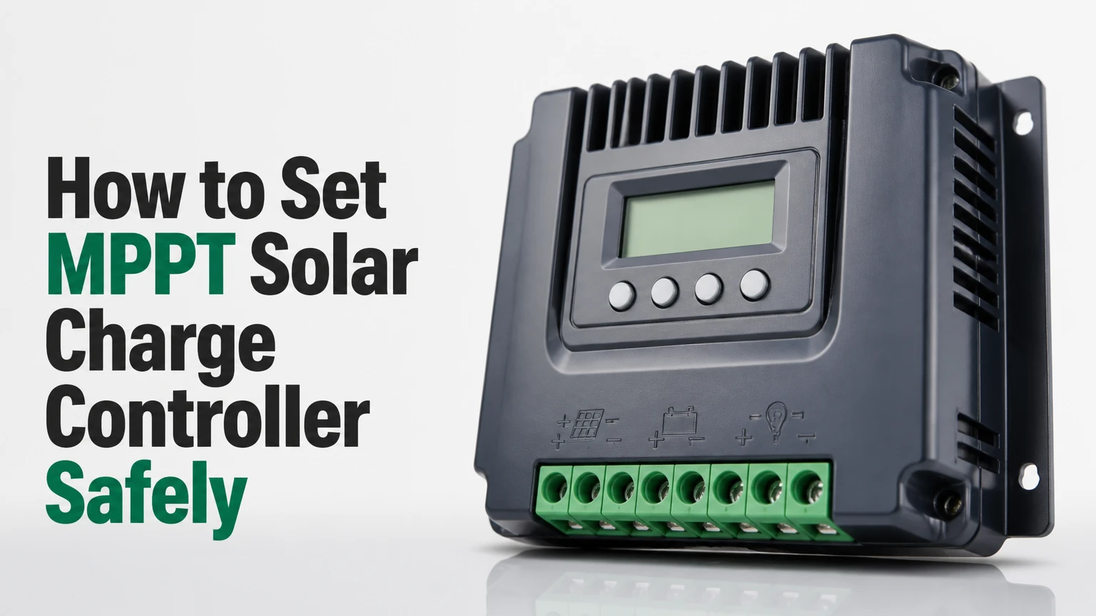
To set an MPPT solar charge controller, calculate the array voltage and current, connect the battery first, select the correct battery chemistry, program manufacturer-approved charging values, then connect and test the solar array. A typical small installation takes 30-90 minutes, but battery specifications and the controller’s maximum cold-weather PV voltage determine the correct settings.
Key Facts
Connect the battery before the photovoltaic array unless the controller manual specifies another sequence.
The controller’s maximum PV voltage applies to the cold-weather corrected array Voc, not merely the panel’s nominal voltage.
LiFePO4 batteries generally require equalization disabled and must follow the battery manufacturer’s voltage and temperature limits.
A 30 A controller on a 12 V battery commonly handles about 400 W of solar, subject to the manufacturer’s power limit.
An inverter should connect directly to the battery through its own fuse, not to the controller’s small load terminals.
MPPT conversion increases usable energy from higher-voltage panels, but it cannot create energy that the array does not receive.
Before You Set the MPPT Controller
Prepare the controller manual, battery datasheet, panel labels, a digital multimeter, insulated screwdrivers, correctly sized copper cable, battery and PV disconnects, and overcurrent protection. Disconnect all sources before handling conductors, remove rings and metal jewelry, and use a qualified electrician for permanently installed or high-voltage systems.
| Preparation item | Typical specification | Purpose | Check before wiring |
|---|---|---|---|
| Digital multimeter | DC voltage, at least 100 V range | Polarity and voltage tests | Leads rated for measured voltage |
| Battery fuse | Sized to cable and controller output | Protects battery cable | Installed near battery positive |
| PV disconnect | DC-rated for array voltage and current | Safe isolation | Voltage rating exceeds cold Voc |
| Battery cable | Often 6-16 mm² for 20-60 A systems | Limits heat and voltage drop | Length and ampacity verified |
| Mounting clearance | Commonly 100-150 mm around vents | Cooling | Dry, shaded, nonflammable surface |
| Setup time | 30-90 minutes | Installation estimate | Longer for custom or 48 V systems |
Mount the MPPT solar charge controller vertically in a dry, ventilated location. Avoid battery compartments containing hydrogen gas, direct sun, engine heat, rain, and enclosed cabinets where the heatsink cannot shed power.
The controller needs four separate electrical decisions: battery chemistry, nominal system voltage, PV operating range, and charging current. A controller marked “12/24 V” does not automatically accept any panel voltage, and a controller marked “30 A” does not automatically accept 30 A from every array configuration.
What Does an MPPT Solar Charge Controller Do?
An MPPT solar charge controller tracks the panel array’s maximum power point and converts that power to the battery’s charging voltage. The controller changes input voltage and output current through a high-frequency DC-to-DC converter, while accounting for conversion losses and its own thermal limits.
A panel’s nameplate includes voltage at maximum power, or Vmp, and current at maximum power, or Imp. Their product approximates rated power:
[ P_{mp}=V_{mp}\times I_{mp} ]
For a 200 W panel rated at 40 Vmp and 5 A Imp, a 12 V battery cannot use 40 V directly. An MPPT controller may convert approximately 200 W of panel power into about 13-15 A at a 14 V charging voltage after conversion losses. A PWM controller instead pulls the panel toward battery voltage, so the result can be substantially lower when the panel has a high Vmp.
MPPT algorithms such as Perturb and Observe and Incremental Conductance estimate the best operating point as sunlight, temperature, and battery voltage change. Tracking is not perfect during rapidly moving clouds, partial shading, or very low irradiance, and stated efficiency is a maximum or typical figure rather than a guaranteed daily result.
Victron Energy’s SmartSolar documentation gives the practical rule, “The battery must be connected first”, for controllers that use battery voltage to initialize their system voltage. That sequence is widespread, but the exact manual for the installed model takes priority because some integrated inverter-chargers and specialized controllers use different procedures.
How Do You Size the Controller and Solar Array?
Size the controller from both its maximum charging current and its maximum PV open-circuit voltage. For a preliminary current estimate, divide array watts by battery nominal voltage, then select a controller whose rated output and manufacturer-approved PV wattage exceed the result.
[ I_{controller}\approx\frac{P_{array}}{V_{battery}} ]
| Battery bank | Typical controller | Approximate array power | Preliminary output current |
|---|---|---|---|
| 12 V | 20 A | 260 W | 21.7 A at 12 V nominal |
| 12 V | 30 A | 400 W | 33.3 A at 12 V nominal |
| 24 V | 30 A | 800 W | 33.3 A at 24 V nominal |
| 48 V | 60 A | 3,200 W | 66.7 A at 48 V nominal |
The table is a planning guide, not a universal rating. For example, a particular 30 A controller may permit 440 W on a 12 V system, while another may limit the array to 400 W. Read the model’s maximum PV power, maximum PV short-circuit current, and maximum output current separately.
Calculate cold-corrected Voc before choosing a series configuration:
[ V_{oc,cold}=V_{oc,STC}\times[1+\text{temperature coefficient}\times(25^\circ C-T_{min})] ]
Use the panel’s negative voltage temperature coefficient from its data sheet. If two 50 V Voc panels are connected in series, the STC string Voc is approximately 100 V. At a cold design temperature, the corrected value can exceed a 100 V controller’s limit, even though the nominal calculation appears acceptable.
| Array example | STC Voc | Cold correction | Design Voc | Suitable controller condition |
|---|---|---|---|---|
| 1 × 400 W panel | 49 V | 8% | 52.9 V | Controller maximum above 52.9 V |
| 2 × 200 W in series | 46 V total | 10% | 50.6 V | 75 V controller may be suitable |
| 3 × 200 W in series | 69 V total | 10% | 75.9 V | 100 V controller provides limited margin |
| 4 × 200 W in series | 92 V total | 10% | 101.2 V | Not suitable for a 100 V controller |
Parallel strings increase current without increasing string voltage. Confirm the controller’s maximum PV short-circuit current, because parallel-array Isc can exceed the input rating even when Voc remains safe.
Step 1: Connect the Battery First
Turn off the PV disconnect and all DC loads. Install the battery fuse near the battery positive terminal, confirm polarity with the multimeter, then connect battery positive and negative to the controller’s battery terminals using the cable size specified for the expected current.
The battery-first sequence lets many MPPT controllers identify a 12 V, 24 V, or 48 V bank and power their control electronics safely. Connecting PV first is not universally guaranteed to destroy a controller, but it can cause incorrect system-voltage detection or damage on models that require battery initialization.
You will know the step worked when the display or application shows battery voltage and the controller identifies the correct nominal system voltage.
Common mistake: Connecting the positive and negative battery cables backward, even briefly. Reverse polarity can blow the battery fuse or destroy the controller, so use a meter at the controller terminals before closing the fuse.
Step 2: Select the Battery Chemistry
Choose the controller profile that matches the battery manufacturer’s chemistry and charging instructions. Select LiFePO4 for a lithium iron phosphate battery, AGM or sealed for the appropriate sealed lead-acid battery, and flooded for a vented lead-acid battery with accessible electrolyte.
Do not select a profile based only on nominal voltage. A 12 V LiFePO4 battery and a 12 V AGM battery have different absorption behavior, float requirements, temperature limits, and acceptable voltage thresholds.
| Battery chemistry | Typical 12 V absorption | Typical float | Equalization | Temperature compensation |
|---|---|---|---|---|
| LiFePO4 | 14.0-14.4 V | 13.4-13.6 V | Disabled | Usually disabled, per battery maker |
| AGM | 14.2-14.7 V | 13.4-13.8 V | Usually disabled | Often enabled with sensor |
| Gel | 14.0-14.4 V | 13.5-13.8 V | Disabled | Usually enabled with sensor |
| Flooded lead-acid | 14.4-14.8 V | 13.2-13.6 V | Enabled only when specified | Enabled with sensor |
These are typical starting ranges for a 12 V bank, not replacement values for a datasheet. Double the voltage for 24 V and multiply by four for 48 V, but confirm whether the controller displays per-bank or total-bank values.
A lithium battery’s internal battery-management system may disconnect charging when cells are full, cold, or outside safe limits. The charge controller should not be configured to fight that BMS behavior. For LiFePO4, disable equalization, confirm the battery permits the chosen absorption voltage, and verify whether charging below 0°C is prohibited.
Step 3: Program Charging Stages and Protection Values
Program bulk, absorption, float, absorption duration or tail-current termination, low-voltage disconnect, and equalization from the battery manufacturer’s instructions. Bulk charging supplies available current, absorption holds a voltage limit while current tapers, and float maintains a lower voltage after the battery reaches the selected state.
| Setting for a 12 V bank | LiFePO4 typical | AGM typical | Flooded typical | Function |
|---|---|---|---|---|
| Absorption voltage | 14.0-14.4 V | 14.2-14.7 V | 14.4-14.8 V | Finishes the main charge |
| Float voltage | 13.4-13.6 V | 13.4-13.8 V | 13.2-13.6 V | Maintains a charged lead battery |
| Absorption duration | 10-30 minutes or maker setting | 2-4 hours | 2-4 hours | Limits high-voltage time |
| Equalization | Off | Off unless specified | 14.8-16.0 V only if specified | Controlled lead-acid service cycle |
| Low-voltage disconnect | Battery/BMS setting | 11.1-11.5 V | 10.8-11.5 V | Protects controller load output |
| Reconnect voltage | 12.4-13.0 V | 12.4-12.8 V | 12.4-12.8 V | Restores controller load output |
Low-voltage disconnect values apply to the controller’s load terminals, not necessarily an inverter wired directly to the battery. Lithium voltage drops less under load than lead-acid voltage, so a voltage-only disconnect can be a poor state-of-charge indicator for LiFePO4.
Set equalization to off for lithium and gel batteries unless the manufacturer explicitly provides a compatible procedure. Flooded lead-acid batteries may require equalization, but the cycle can release hydrogen and oxygen, consume water, and damage sealed batteries.
You will know the step worked when the application displays the selected chemistry, voltage limits, and equalization status without a warning or profile mismatch.
Common mistake: Copying a generic internet voltage table into USER mode. Manufacturer values differ by cell construction, temperature, maximum charge rate, and BMS design.
Step 4: Connect and Verify the Solar Array
Keep the PV disconnect open while checking the array. Measure the array’s open-circuit voltage, verify positive and negative polarity, compare the measured value with the expected string Voc, and connect the PV conductors only after the battery side is active.
Use a DC-rated breaker or isolator on the PV positive conductor where required by the installation design. A breaker must be rated for the array’s maximum voltage and current; an AC-only breaker may not interrupt a solar DC arc safely.
You will know the step worked when the controller reports PV voltage above battery voltage and begins a charging stage when sunlight is sufficient. Many buck-type MPPT controllers need PV voltage several volts above present battery voltage, but the exact startup margin belongs to the model specification.
Common mistake: Checking only panel polarity and ignoring series-string voltage. A correct polarity does not make an over-voltage array safe.
Step 5: Connect Loads Correctly
Connect only appropriately rated low-current DC loads to the controller’s load terminals. Connect an inverter, high-starting-current motor, refrigerator, or large DC distribution panel directly to the battery through a separately sized fuse and disconnect.
| Load type | Typical connection | Why | Example protection |
|---|---|---|---|
| 12 V LED lighting | Controller load terminal | Low steady current | 5-10 A fuse |
| USB charging outlet | Controller load terminal | Small DC load | 5-10 A fuse |
| 600 W inverter | Battery bus | About 50 A at 12 V | 80-100 A fuse, per maker |
| 2,000 W inverter | Battery bus | More than 165 A at 12 V | Large battery fuse and busbars |
| Water pump | Battery distribution | Motor startup surge | Fuse sized to motor data |
The controller load output may include low-voltage disconnect, timer, and streetlight functions, but its rating is commonly much lower than the battery’s available fault current. Never use the load terminals as a substitute for a fused DC distribution system.
How Do You Commission the System?
Commission the MPPT solar charge controller with five measurements: battery voltage at the controller, PV polarity, PV open-circuit voltage, charging current, and terminal temperature under load. Record the values at startup and again after 20-30 minutes of strong sunlight.
| Commissioning test | Typical acceptable result | Instrument or display | Action if abnormal |
|---|---|---|---|
| Battery polarity | Positive and negative match labels | Multimeter | Open fuse and correct wiring |
| Battery voltage | Within battery maker’s operating range | Multimeter | Charge or inspect battery |
| PV Voc | Within calculated cold-safe controller range | Multimeter | Open PV disconnect and reconfigure |
| PV operating voltage | Above battery voltage by model margin | Controller app | Check shading and string design |
| Charging current | Consistent with sun, array, and battery state | Clamp meter or app | Compare with expected power |
| Cable temperature | Slightly warm, not hot or discolored | Touch only after isolation, or IR meter | Isolate and inspect cable, fuse, torque |
Compare the controller display with a meter at the battery terminals. A small difference is expected because cable voltage drop and measurement locations differ. A large difference points to loose terminals, undersized cable, a failing fuse, or a faulty sensor.
Do not judge array performance from one cloudy reading. Panel output changes with irradiance, panel temperature, angle, shading, battery acceptance, and controller temperature. A fully charged battery can also cause the controller to reduce current even when the array could produce more.
Which MPPT Settings Change With System Voltage?
The charging voltage scales with the number of series-connected battery cells, while current capacity and cable requirements do not scale in the same way. A 400 W array produces roughly twice the current at 12 V compared with 24 V, which makes higher-voltage battery banks useful for longer cable runs and larger systems.
| System nominal voltage | Example battery arrangement | 14.4 V equivalent charge setting | 400 W ideal charge current |
|---|---|---|---|
| 12 V | 4 LiFePO4 cells in series | 14.4 V | 33.3 A |
| 24 V | 8 LiFePO4 cells in series | 28.8 V | 16.7 A |
| 48 V | 16 LiFePO4 cells in series | 57.6 V | 8.3 A |
| 24 V lead-acid | Two 12 V batteries in series | 28.8 V | 16.7 A |
A controller can detect nominal voltage incorrectly if a partially discharged battery is connected or if the battery cable has excessive voltage drop. Confirm the displayed system voltage before connecting PV.
MPPT Versus PWM: Which Controller Fits?
MPPT is usually the better choice when panels have a Vmp substantially above battery charging voltage, the array is large, the wiring run is long, or winter conditions reduce panel temperature. PWM can remain practical for a small 12 V system using a panel designed specifically for 12 V battery charging.
| Criterion | MPPT controller | PWM controller | Practical consequence |
|---|---|---|---|
| Panel Vmp flexibility | Often 30-100+ V input | Near battery charging voltage | MPPT accepts higher-voltage strings |
| Typical conversion efficiency | Approximately 95-99% | Lower when panel voltage is mismatched | MPPT captures more usable power |
| Small-system purchase price | Commonly $60-$600+ | Commonly $15-$100 | PWM costs less initially |
| Long cable suitability | Higher PV voltage reduces current | Low voltage requires larger cable | MPPT can reduce copper size |
| Partial-shade behavior | Can track array operating point | Panel mismatch remains significant | Neither fixes severe shade |
| Best use case | RV, cabin, residential array | Small matched 12 V panel | Match controller to array design |
The often-repeated claim that MPPT always produces 30% more energy is not universal. The gain depends on panel Vmp, battery voltage, temperature, wiring, and sunlight; a matched 12 V panel under strong sun may show a small advantage, while a high-voltage residential panel on a 12 V battery can show a much larger practical difference.
What Does an MPPT Controller Cost?
Typical 2026 retail pricing ranges from about $20-$60 for basic 10-30 A units, $80-$180 for many 30-60 A RV and residential controllers, and $200-$600 or more for networked professional equipment. Import duties, certification, Bluetooth, communication protocols, warranty, and maximum PV voltage create major regional differences.
| Controller class | Typical price | Common rating | Suitable application | Main limitation |
|---|---|---|---|---|
| Basic hobby unit | $20-$60 | 10-30 A, 75-100 V PV | Small cabin or lighting | Limited documentation |
| Mid-range controller | $80-$180 | 30-60 A, 100-150 V PV | RV or small home | Fewer integration options |
| Premium networked unit | $200-$600+ | 30-100 A, 100-250 V PV | Professional off-grid system | Higher installation cost |
| Integrated inverter-charger | $400-$2,000+ | Model-dependent | Larger standalone system | More complex configuration |
Choose documentation and protection ratings before app features. A low-cost controller with an unclear battery profile, inaccurate ratings, or no cold-weather Voc guidance can cost more after a wiring failure than a properly specified mid-range model.
Common Mistakes and How to Fix Them
Why Is the Controller Blank?
A blank display usually results from an open battery fuse, incorrect polarity, a disconnected battery, or battery voltage below the controller’s startup threshold. Measure voltage directly across the controller’s battery terminals, not only at the battery posts.
If battery voltage exists at the battery but not at the controller, inspect the fuse, disconnect, cable lugs, and terminal torque. If voltage is present and polarity is correct, isolate PV and loads, then consult the manufacturer before replacing the unit.
Why Is Solar Current Zero?
Zero solar current can occur when the PV disconnect is open, the array is shaded, polarity is reversed, PV voltage is below startup voltage, or the battery has reached its charge limit. Check PV Voc with the array isolated, then check operating voltage with the PV circuit closed.
A panel string can show normal Voc while producing almost no current because of a blown bypass-diode path, damaged cable, severe shade, or a loose connector. Voltage alone does not prove that the array can deliver power.
Why Does the Controller Overheat?
Overheating usually indicates high charging current, poor ventilation, undersized conductors, loose terminals, direct solar heating, or operation above the rated ambient temperature. Mount the controller on a nonflammable vertical surface and follow the manual’s clearance requirement, commonly 100-150 mm.
Do not place a temperature-sensitive controller inside a sealed battery box. Thermal derating can reduce charge current before a visible fault appears.
Why Does Lithium Charging Stop Suddenly?
A LiFePO4 BMS may open its charge path because of low temperature, high cell voltage, cell imbalance, excessive current, or communication failure. The controller cannot correct a BMS trip by raising its charging voltage.
Inspect the battery app for cell and temperature alarms, confirm the controller’s maximum current, and follow the battery manufacturer’s reset procedure. Never bypass a BMS or repeatedly reconnect charging during an unresolved fault.
Why Does Battery Voltage Look Too High?
A high displayed voltage can result from absorption charging, equalization accidentally enabled, a missing or faulty remote temperature sensor, poor calibration, or a battery disconnecting under charge. Open the PV disconnect if the voltage exceeds the battery manufacturer’s limit, then verify with a multimeter.
A temperature sensor can change lead-acid charging voltage significantly. Do not use lead-acid temperature compensation settings for LiFePO4 unless the battery manufacturer explicitly approves them.
How Should You Adapt the Setup for Different Situations?
A weekend RV normally benefits from a 30-40 A Bluetooth controller, provided the roof array, battery capacity, and cable length fit the model. A small cabin may prioritize low price and simple AGM programming, while a full-time off-grid home needs documented ratings, remote monitoring, coordinated inverter settings, and serviceable protection equipment.
For partial shade, avoid placing differently shaded panels in one series string when the design allows separate MPPT inputs or parallel strings. For long distances, raise PV voltage within the controller’s cold-safe limit rather than sending high current at low voltage, then calculate voltage drop for both PV and battery conductors.
For two controllers charging one battery bank, configure compatible absorption and float voltages, use separate appropriately rated fuses, place battery-voltage sensing at a common bus, and confirm that lithium BMS communication or charge-current limits are coordinated. Two controllers do not double the safe charging current beyond the battery’s specified limit.
FAQ
Can I Set an MPPT Controller Without a Battery?
Most standalone MPPT battery controllers should not be configured or energized from PV alone because they use the battery connection for startup and system-voltage detection. Some specialized units support PV-first operation, so the installed model’s manual controls. Do not connect an unverified controller to solar first.
How Many Watts Can a 30 A MPPT Controller Handle?
A 30 A controller commonly handles approximately 400 W on a 12 V system and approximately 800 W on a 24 V system, but the manufacturer’s maximum PV wattage overrides the estimate. The array must also remain below maximum Voc and short-circuit-current limits in cold conditions.
Should I Use Equalization on an AGM Battery?
Usually no. AGM manufacturers commonly prohibit equalization or specify a narrow service voltage, while flooded lead-acid manufacturers may require it under controlled conditions. Use the battery datasheet rather than assuming every lead-acid battery accepts the same equalization cycle.
Can a 100 V Controller Use Two 50 V Panels in Series?
Only if the cold-corrected combined Voc remains below 100 V with the manufacturer’s required safety margin. Two panels with 50 V Voc each already produce approximately 100 V at standard test conditions, leaving no margin for the voltage rise that occurs in cold weather.
Does an MPPT Controller Charge Faster Than a PWM Controller?
An MPPT controller can deliver more charging power when panel voltage is substantially higher than battery charging voltage, but charging speed also depends on sunlight, battery acceptance, temperature, and controller limits. MPPT improves electrical conversion; it does not increase available sunlight or a battery’s safe charge rate.
Why Does My Controller Show PV Voltage but No Amps?
PV voltage without current often means the array is disconnected under load, heavily shaded, incorrectly fused, limited by a full battery, or unable to supply current because of a bad connector or damaged panel. Test voltage and current under operating conditions, not only open-circuit voltage.
The Bottom Line
Set an MPPT solar charge controller by verifying the battery chemistry, battery-bank voltage, array cold-weather Voc, controller current rating, and cable protection before energizing the system. Connect the battery first when the manual requires it, disable lithium equalization, connect PV through a DC-rated isolator, and confirm charging with measured values rather than trusting a single display.
The safest answer to how to set mppt solar charge controller is therefore a controlled commissioning process, not a generic voltage table. Use the battery and controller manufacturers’ specifications for final settings, and stop the installation when polarity, temperature, voltage, or BMS behavior does not match the expected result.