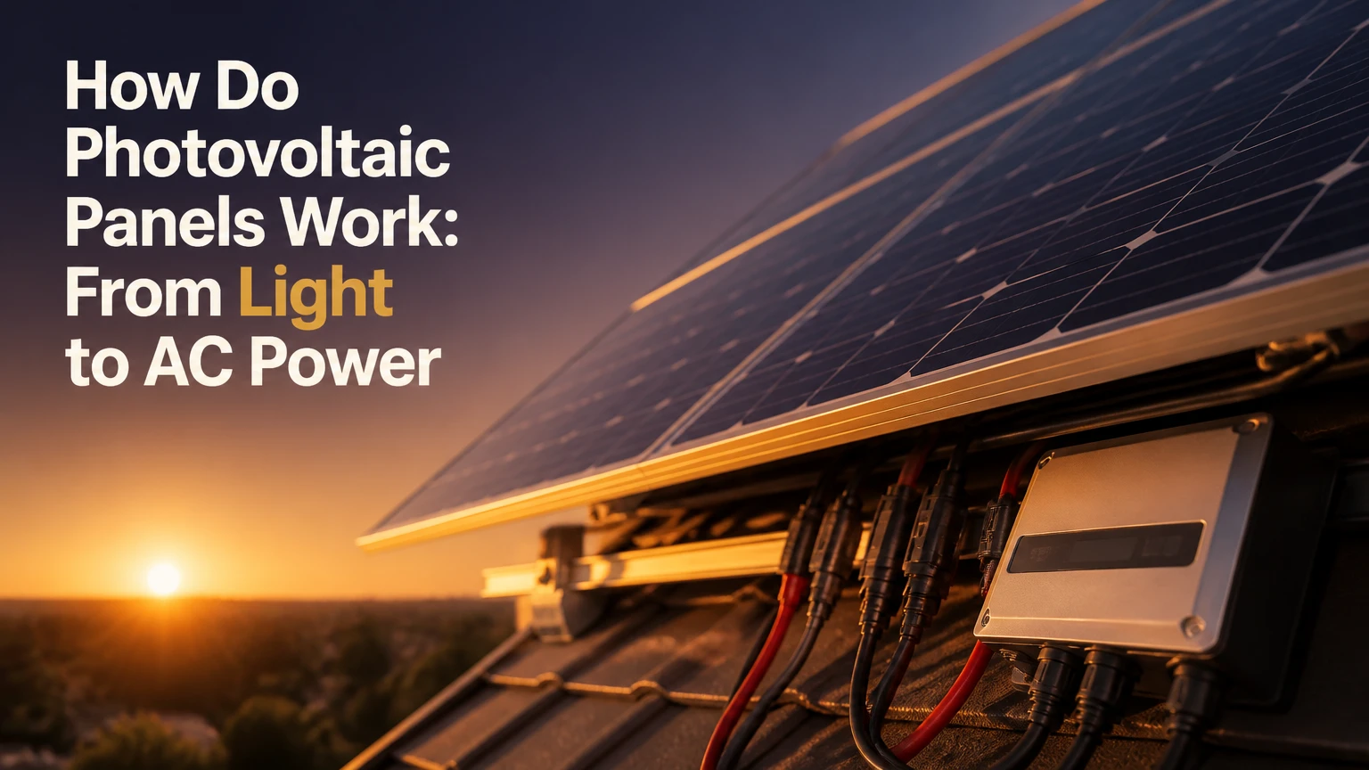
Photovoltaic panels convert sunlight directly into direct-current electricity through the photovoltaic effect in semiconductor cells. Photons transfer energy to electrons in materials such as silicon, an internal electric field separates the resulting charges, and metal contacts collect the electrons as current. An inverter then converts that DC electricity into grid-compatible alternating current.
Key Facts at a Glance
- A photovoltaic cell converts light into electricity, while a solar thermal collector converts sunlight into heat.
- Silicon cells generate DC electricity because separated electrons move through an external circuit in one direction.
- A photovoltaic module contains many interconnected cells protected by glass, encapsulant, a backsheet or second glass layer, and a frame.
- A grid-tied inverter converts the array’s DC output into AC electricity for appliances, export, or both.
- Standard Test Conditions rate modules at 1,000 W/m² irradiance and 25°C cell temperature, but operating cells are often much hotter.
- A grid-tied solar system normally shuts down during a utility outage unless approved battery backup equipment isolates the home from the grid.
What Is a Photovoltaic Panel?
A photovoltaic panel, also called a PV module, is an engineered assembly of solar cells that produces DC electricity from light without combustion or moving mechanical parts. The active cells usually contain crystalline silicon, although thin-film materials such as cadmium telluride and copper indium gallium selenide are also used.
The term matters because “panel,” “module,” “cell,” and “array” describe different physical scales.
| Term | Physical meaning | Typical example | Electrical role |
|---|---|---|---|
| Photovoltaic cell | One semiconductor light-conversion unit | Silicon cell, about 15-30 cm wide | Produces roughly 0.5-0.7 V |
| Module or panel | Encapsulated group of cells | 400-700 W rooftop module | Delivers usable DC output |
| String | Series-connected modules | 10-14 modules on one roof section | Raises DC voltage |
| Array | All connected modules at a site | 8 kW residential array | Supplies the inverter |
| PV system | Array plus electrical equipment | Panels, inverter, racking, meter, battery | Produces, manages, and distributes energy |
The photovoltaic effect was first observed by Edmond Becquerel in 1839. Modern silicon cells apply that effect through controlled semiconductor junctions, conductive contacts, optical coatings, and electrical power electronics.
Photovoltaic technology is not the same as concentrated solar power. Concentrated solar plants use mirrors to heat a working fluid, whereas PV cells create electrical charge directly inside a solid semiconductor.
How Do Photovoltaic Panels Work?
Photovoltaic panels work through five linked events: photons enter the cell, semiconductor electrons absorb enough energy to move, an electric field separates electrons and holes, metal contacts collect the charges, and an inverter converts the resulting DC into AC. The panel does not store sunlight or make electricity from heat alone.
1. Light Enters the Semiconductor
Sunlight contains photons with different energies and wavelengths. An anti-reflective coating and textured cell surface reduce reflection so more photons enter the silicon rather than returning to the atmosphere.
A silicon atom has electrons arranged in energy levels. In a solid silicon crystal, neighboring atoms share electrons through covalent bonds. A photon with energy at or above silicon’s band gap can transfer energy to a bound electron and move that electron into a mobile conduction state.
The band gap creates a fundamental selection rule. Photons with too little energy pass through or become heat, while photons with much more energy lose their excess energy as heat after creating a charge carrier.
2. Silicon Creates an Electron-Hole Pair
When a suitable photon frees an electron, the missing electron position is called a hole. The electron and hole form an electron-hole pair, although the hole is not a positively charged particle moving like a proton. It is an effective positive charge created by the movement of neighboring electrons.
The U.S. Department of Energy summarizes the central mechanism as follows: “When sunlight strikes a solar cell, it creates an electric field.” That field is produced by the cell’s semiconductor junction and gives the newly created charges a preferred direction.
Some electron-hole pairs recombine before collection. Recombination reduces output, which is why modern cells use surface passivation and selective contacts to prevent carriers from disappearing before reaching the circuit.
3. The P-N Junction Separates Charge
Manufacturers alter silicon’s electrical behavior through doping. Phosphorus adds donor electrons and creates n-type silicon; boron creates p-type silicon with holes as the majority carriers. Joining the two regions produces a depletion region and a built-in electric field.
The field drives electrons toward the n-type side and holes toward the p-type side. The field does not generate energy by itself. Sunlight supplies the energy, while the junction reduces the chance that useful carriers will immediately recombine.
The common description of the junction as a “one-way valve” is useful for beginners but incomplete for engineering purposes. A PV cell is a diode with a photovoltaic operating mode, and its current-voltage behavior depends on illumination, temperature, recombination, and the external load.
4. Metal Contacts Collect DC Current
Fine front contacts collect electrons from the illuminated side, while rear contacts complete the electrical path. Fingers connect to larger busbars, and ribbons connect cells in series inside the module.
Series wiring adds voltage while keeping approximately the same current. Parallel wiring adds current while keeping approximately the same voltage. A module’s nameplate voltage therefore differs from the voltage of a complete rooftop string.
| Electrical quantity | What it measures | Typical module example | Practical consequence |
|---|---|---|---|
| Rated power, Pmax | Maximum power under test conditions | 450 W | Determines array capacity |
| Operating voltage, Vmp | Voltage at maximum power | 41 V | Used for inverter tracking |
| Operating current, Imp | Current at maximum power | 11 A | Affects conductor sizing |
| Open-circuit voltage, Voc | Voltage with no load | 49 V | Used for cold-weather design |
| Short-circuit current, Isc | Current with terminals shorted | 11.5 A | Used for protection calculations |
| Efficiency | Sunlight converted to rated electricity | 22.5% | Determines area per watt |
A cell produces direct current because the collected charge moves through the external circuit from the negative electrical terminal toward the positive terminal. Conventional current is defined in the opposite direction, from positive to negative.
5. The Inverter Produces Usable AC
A solar inverter rapidly switches and shapes the incoming DC waveform into alternating current with the voltage, frequency, phase, and safety controls required by the local electrical network. The inverter also tracks the array’s maximum power point as sunlight and temperature change.
String inverters connect several modules to a centralized power converter. Microinverters attach to individual modules and can reduce the impact of uneven shade. Hybrid inverters add battery charging and backup functions.
The inverter is not an optional accessory for ordinary household use. Most appliances and utility networks require AC, while PV modules naturally produce DC.
What Is Inside a Photovoltaic Module?
A photovoltaic module sandwiches electrically active cells between protective materials that limit moisture, mechanical stress, ultraviolet exposure, and corrosion. The common construction uses low-iron tempered glass, encapsulant, silicon cells, a second encapsulant layer, and either a polymer backsheet or rear glass.
| Module layer or component | Typical material | Main function | Failure concern |
|---|---|---|---|
| Front cover | 3-4 mm low-iron tempered glass | Transmits light and resists hail | Cracks, abrasion, heavy soiling |
| Encapsulant | EVA or POE polymer | Bonds and insulates cells | Moisture ingress, delamination |
| Solar cells | Crystalline silicon or thin film | Converts photons into DC power | Microcracks, degradation |
| Rear protection | Fluoropolymer backsheet or glass | Blocks moisture and insulates | Cracking, seal failure |
| Frame | Anodized aluminum | Adds stiffness and mounting points | Corrosion, poor grounding |
| Junction box | Polymer enclosure with cables | Houses terminals and bypass diodes | Heat damage, loose connectors |
| Bypass diodes | Semiconductor diodes | Route current around shaded substrings | Thermal failure, hot spots |
A bypass diode does not primarily prevent current from flowing backward through the whole panel. Its main job is to provide an alternate path around a shaded or damaged group of cells, reducing reverse-bias stress and hot-spot risk.
Some modules use glass-glass construction instead of a polymer backsheet. Glass-glass modules can improve moisture resistance and support bifacial operation, but they may weigh more and require mounting systems designed for their mechanical loads.
Which Panel Technology Fits Which Situation?
For most new installations, high-efficiency monocrystalline modules are the practical default, while thin film suits selected large or lightweight projects and bifacial modules require a reflective rear environment. TOPCon, HJT, and back-contact designs improve carrier management, but the best choice depends on roof area, temperature, shade, weight, and price.
| Technology | Typical module efficiency | Temperature coefficient | Best-fit situation | Main limitation |
|---|---|---|---|---|
| Monocrystalline PERC | 20%-23% | About -0.30% to -0.35%/°C | Cost-sensitive roofs | More degradation than leading n-type designs |
| Monocrystalline TOPCon | 21%-24% | About -0.28% to -0.32%/°C | Standard homes and businesses | Slight price premium |
| HJT silicon | 21%-24% | About -0.24% to -0.29%/°C | Hot climates and high-density roofs | Higher manufacturing and balance-of-system costs |
| Back-contact IBC or BC | 22%-26% | About -0.27% to -0.30%/°C | Small roofs and appearance-sensitive sites | Premium purchase price |
| Polycrystalline | 15%-18% | About -0.35% to -0.45%/°C | Existing low-cost or legacy systems | Larger area per watt |
| Cadmium telluride thin film | 16%-20% | About -0.20% to -0.30%/°C | Large commercial sites | Lower power density on small roofs |
| Perovskite-silicon tandem | Above standard silicon in laboratory and pilot products | Commercial data still developing | Emerging high-efficiency applications | Long-term durability and scale remain limited |
Monocrystalline cells come from a continuous crystal structure, allowing efficient transport through the wafer. Polycrystalline cells form from multiple crystal grains and historically cost less, but current mainstream manufacturing has shifted strongly toward monocrystalline designs.
TOPCon adds a very thin oxide and passivated contact structure. HJT combines crystalline silicon with thin amorphous silicon layers. Back-contact cells move most or all front-side metal to the rear, reducing front shading and improving appearance.
Bifacial modules are a configuration rather than a separate semiconductor family. Their rear output depends on mounting height, ground reflectivity, row spacing, and rear-side shade. A white membrane or pale gravel can improve albedo, while a dark roof may provide little gain.
What Determines Real-World Solar Output?
A module’s watt rating is a laboratory maximum, not a daily energy promise. Real output depends on irradiance, cell temperature, orientation, tilt, shading, dirt, inverter efficiency, wiring loss, module mismatch, and local weather.
Standard Test Conditions use 1,000 W/m² irradiance, 25°C cell temperature, and an air mass of 1.5. Outdoor cell temperature commonly reaches 45-75°C, so a module rated at 25°C can produce less peak power on a hot roof.
For a 450 W module with a -0.30%/°C power coefficient, a 65°C cell temperature is 40°C above the rating condition. The approximate temperature loss is 12%, producing about 396 W before other losses.
A simple annual estimate uses:
Annual energy = system size × local peak-sun equivalent hours × 365 × performance ratio
For an 8 kW system receiving 4.5 equivalent sun hours daily and achieving a 0.80 performance ratio:
8 × 4.5 × 365 × 0.80 = 10,512 kWh per year
That is a planning estimate, not a guarantee. A production model such as NREL’s PVWatts should include roof orientation, tilt, weather data, shading, and system losses.
| Output factor | Typical effect | Example condition | Planning response |
|---|---|---|---|
| Temperature | -0.20% to -0.45%/°C above 25°C | 65°C cell temperature | Compare temperature coefficients |
| Inverter conversion | 1%-4% loss | 96%-99% weighted efficiency | Check efficiency curve |
| Wiring and mismatch | 1%-3% loss | Long DC runs or mixed modules | Minimize cable length |
| Soiling | 2%-10% typical, higher in dusty areas | Pollen, dust, bird droppings | Inspect and clean safely |
| Shading | 5%-100% local loss | Chimney shade on a string | Use layout changes or module electronics |
| Annual degradation | About 0.25%-0.50%/year for many modern modules | Long-term exposure | Compare product warranties |
A counterintuitive design rule is that a higher-wattage panel does not always produce more annual energy per panel. If the larger module cannot fit around vents or must be installed in a shaded row, a smaller, better-positioned module can produce more useful energy.
What Happens in Clouds, Shade, and at Night?
Photovoltaic panels continue producing electricity under clouds because diffuse skylight still contains photons, but output can fall substantially compared with clear midday conditions. Photovoltaic panels produce no meaningful electricity at night, and shade can reduce a string’s output more than its covered area suggests.
Cloud thickness, solar elevation, weather, and panel orientation determine the reduction. Light overcast may leave a system producing 30%-70% of clear-sky output, while dense storm clouds can reduce output to single-digit percentages. These are typical ranges, not universal performance guarantees.
Shade is electrically uneven. A small shadow across one cell substring can force a bypass diode to conduct, removing that substring from the module’s contribution. Shade from a tree that moves across several modules can therefore cause a larger loss than the shaded surface area alone implies.
Panel-level power optimizers and microinverters can limit mismatch between modules, but they cannot create sunlight or recover energy blocked from the shaded cells. Layout changes remain the strongest solution.
How Do Batteries and Inverters Change the System?
Batteries store surplus DC or AC energy for later use, while hybrid inverters control charging, discharging, grid interaction, and backup circuits. A battery changes when electricity is available, but it does not increase the solar energy collected by the panels.
| System configuration | Daytime energy path | Nighttime energy path | Blackout behavior |
|---|---|---|---|
| Grid-tied string inverter | PV to inverter to loads and grid | Grid to household loads | Usually shuts down |
| Grid-tied microinverters | Each module converts DC to AC | Grid supplies loads | Usually shuts down |
| Hybrid solar and battery | PV to loads, battery, or grid | Battery to backup loads | Operates if approved islanding exists |
| Off-grid system | PV to loads and battery | Battery to inverter and loads | Operates independently |
| AC-coupled battery | PV inverter to AC bus, battery inverter charges | Battery inverter supplies AC bus | Requires backup controls |
Most grid-tied systems shut down during an outage to prevent unintentional energization of utility lines. A battery system needs an automatic transfer device or equivalent certified islanding equipment to disconnect the protected loads from the grid.
Battery sizing requires two separate decisions. Power capacity, measured in kW, determines which appliances can run simultaneously; energy capacity, measured in kWh, determines how long they can run.
How Does Photovoltaic Power Compare With Alternatives?
Photovoltaic power converts light directly into electricity, while solar thermal systems convert sunlight into heat and conventional generators convert chemical energy into mechanical and electrical energy. The right technology depends on the needed energy form, operating schedule, available fuel, and grid connection.
| Technology | Primary output | Moving parts | Night operation | Typical application |
|---|---|---|---|---|
| PV module | DC electricity | No | Only with storage or grid supply | Rooftops, ground arrays |
| Solar thermal collector | Hot water or heat | Pumps may operate | Storage tank required | Domestic hot water |
| Concentrated solar power | Heat, then electricity | Turbines and pumps | Thermal storage possible | Utility-scale generation |
| Natural-gas generator | AC electricity and waste heat | Yes | Yes with fuel | Backup or dispatchable supply |
| Wind turbine | AC electricity | Yes | Yes when wind is available | Utility and rural sites |
Photovoltaic panels are a poor substitute for a hot-water collector when the primary requirement is domestic water heating. PV can still power a heat-pump water heater, but the combined equipment changes the efficiency and cost calculation.
What Does a Photovoltaic System Cost?
Typical installed residential PV costs range from approximately $2.30-$3.60 per watt in the United States before incentives, making an 8 kW system roughly $18,400-$28,800. Local labor, roof complexity, electrical upgrades, permitting, financing, batteries, and utility requirements can move the final price far outside that range.
| Region | Typical residential system | Indicative installed cost | Typical installation time |
|---|---|---|---|
| United States | 8 kW | $18,400-$28,800 before incentives | 1-2 site days after approvals |
| United Kingdom | 3-5 kW | £3,500-£10,000 | 1-2 site days |
| Australia | 3 kW | About AUD 4,000 | 1 site day in simple cases |
| Australia | 8 kW | Up to about AUD 7,700 in common market quotes | 1-2 site days |
| Bangladesh | 1-3 kW | BDT 80,000-BDT 250,000 or more | Varies by equipment and site |
| Bangladesh | 5-10 kW | BDT 400,000-BDT 1,300,000 or more | Varies by approvals and design |
A typical project requires one to three days for site assessment, two to six weeks for permitting and interconnection, and one to two days for physical residential installation. The approval period often exceeds the roof work.
The cheapest quote can hide undersized conductors, unsuitable mounting hardware, poor monitoring, or an inverter without adequate service support. Compare the module warranty, inverter replacement terms, workmanship warranty, expected annual energy, and total installed price rather than panel wattage alone.
What Problems Reduce Photovoltaic Output?
Reduced PV output usually comes from weather, shade, soiling, equipment faults, or incorrect expectations about the system’s rated power. A production decline that persists under comparable sunlight deserves investigation through inverter data, visual inspection, and qualified electrical testing.
One String Produces Zero
A zero-output string can result from a tripped DC isolator, blown fuse, disconnected connector, damaged cable, or inverter input fault. Read the inverter event log first, then have a qualified technician isolate the circuit and measure string voltage against the design value.
Do not disconnect energized PV connectors in sunlight. DC arcs can persist and cause burns or fire.
Output Falls Gradually
Dust, pollen, bird droppings, new shade, module degradation, and inverter clipping can cause a gradual decline. Compare the current production with the same month in prior years while accounting for weather, then inspect the modules during cool conditions.
Clean only when the manufacturer permits it. Use clean water and a non-abrasive method, avoiding cold water on hot glass because thermal shock can damage modules.
The Inverter Reports a Ground Fault
Ground-fault warnings can indicate damaged insulation, wet connectors, rodent damage, or a fault inside a module or inverter. Turn off the system according to the manufacturer’s shutdown procedure and arrange an insulation-resistance test rather than repeatedly resetting the alarm.
Expert Installation Rules
- Design for the coldest expected temperature, because open-circuit voltage rises as cells become colder and can exceed inverter limits.
- Keep module connectors off the roof surface, where standing water and ultraviolet exposure accelerate failure.
- Treat shade analysis as an electrical design task, not merely a roof photography exercise.
- Match battery power to the starting surge of pumps, refrigerators, and compressors, not only their running wattage.
Frequently Asked Questions
Do photovoltaic panels work in winter?
Yes. Photovoltaic panels can produce strongly in cold weather because lower cell temperature generally improves voltage and power. Winter production may still be lower because days are shorter, the sun is lower, snow covers the modules, and clouds reduce irradiance. Snow that slides away can leave clean glass and useful output.
Can photovoltaic panels charge a battery directly?
Yes, but a charge controller or compatible hybrid inverter must regulate the PV voltage and current before battery charging. Modern lithium iron phosphate batteries require battery-management communication and correctly configured voltage limits. Connecting a panel directly to a battery can cause overcharging, equipment damage, or a safety hazard.
How long do photovoltaic panels last?
Many modern modules carry product and performance warranties lasting 25-30 years, with warranted output commonly remaining around 85%-90% of the initial rating near the end of that period. The glass, encapsulant, connectors, inverter, and mounting structure age differently, so system life is not determined by the cells alone.
Are photovoltaic panels recyclable?
Yes, glass, aluminum frames, silicon, copper, and some semiconductor materials can be recovered, although recycling availability and economics vary by country. Aluminum frames and glass generally provide the easiest material recovery. Ask the installer or manufacturer about take-back programs before replacing damaged modules.
Do photovoltaic panels increase roof temperature?
A panel can shade the roof and alter heat transfer, while the panel itself becomes hot in sunlight. Research on roof assemblies finds that the effect depends on an air gap, roof material, ventilation, mounting layout, and climate. Properly installed rooftop modules are not a substitute for roof insulation or ventilation.
Why do photovoltaic panels lose power when they get hot?
Photovoltaic panels lose power as cell temperature rises because voltage decreases faster than current increases. A module with a -0.30%/°C coefficient loses approximately 12% of rated power when its cells reach 65°C under otherwise comparable conditions, since that temperature is 40°C above the 25°C rating point.
The Bottom Line
How do photovoltaic panels work? Photovoltaic panels absorb photons in semiconductor cells, create electron-hole pairs, separate those charges through a p-n junction field, and collect the electrons as DC electricity. Solar inverters then convert the DC output into AC for appliances, batteries, or the utility grid.
Panel type affects efficiency, temperature response, degradation, weight, and area requirements. Real-world production depends at least as much on orientation, shade, heat, soiling, inverter design, and system losses as on the module’s headline wattage. A sound design therefore evaluates the whole photovoltaic system, not the panel label alone.