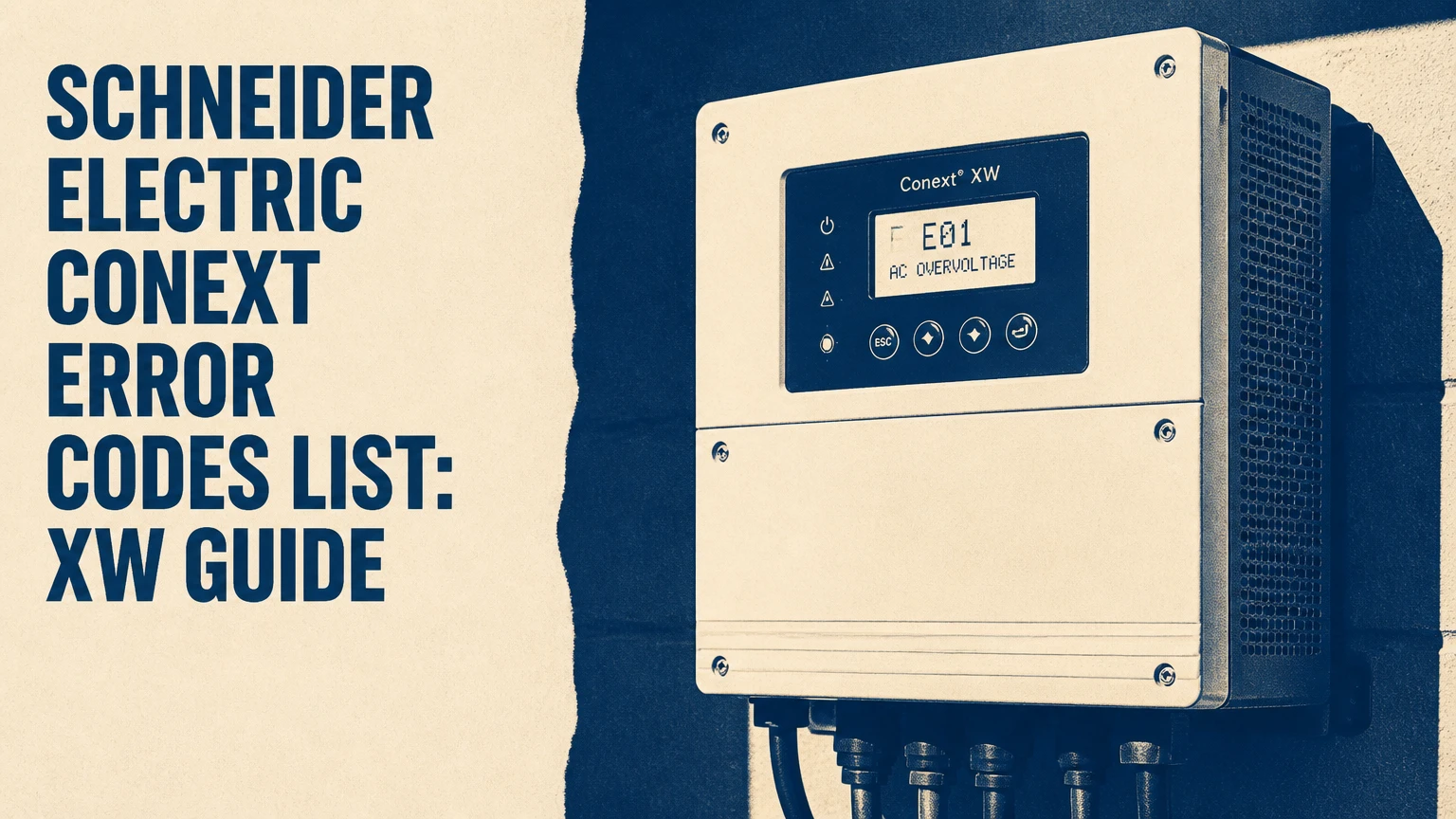
The Schneider Electric Conext error codes list uses fault codes beginning with F and warning codes beginning with W to report electrical, thermal, communication, configuration, and hardware conditions. Code meanings are model and firmware dependent, so the exact XW, XW+, XW Pro, or SW manual remains authoritative before resetting, replacing parts, or changing protection settings.
Key Facts at a Glance
- F-codes generally indicate a protective fault; W-codes generally indicate a warning or derated operating condition.
- F17-F20 indicate suspected welded AC transfer relay conditions and are not homeowner-reset repairs.
- F47-F49 commonly involve battery voltage, low-battery cutoff, high-battery cutoff, cable drop, or battery protection.
- F63-F65 point toward AC overload or excessive surge demand, especially during motor starting.
- F66, F69, and F70 are commonly associated with configuration, synchronization, Xanbus, or phase-operation problems.
- A code shown by Insight, the System Control Panel, or the inverter display must be matched to the exact model and firmware revision.
What Do Conext F-Codes and W-Codes Mean?
Conext F-codes identify protective shutdowns or serious operating conditions, while W-codes identify warnings that may allow reduced operation. A warning can disappear when the measured condition returns to range; an automatic fault may also recover, whereas a manual or latched fault normally requires deliberate clearing, reconfiguration, or service.
Schneider Electric’s Conext XW Pro Owner’s Guide uses the practical distinction that a fault is a condition that causes the inverter/charger to stop operating, while a warning reports a condition that can affect operation without necessarily stopping the unit. The exact recovery behavior is firmware-specific.
The code prefix does not tell you whether the underlying cause is inside the inverter. For example, an undervoltage code can result from a weak battery, undersized conductors, loose terminals, a failing disconnect, or an incorrect cutoff setting. A grid code can originate at the utility service, an upstream breaker, a generator, or an inverter sensing circuit.
Automatic, Escalating, and Manual Faults
| Classification | Typical behavior | Example family | Usual next action |
|---|---|---|---|
| Warning | Output may continue or derate | W44, W57, W63 | Correct the operating condition |
| Automatic fault | Stops or limits operation, then retries | F23-F40, F44, F57 | Verify stable conditions and observe retry |
| Escalating fault | Repeated automatic trips can latch | F48, F63-F65 | Remove the cause before clearing |
| Manual fault | Remains active until intervention | F17-F20, F51-F56, F66 | Stop repeated resets and obtain service |
The often-repeated “three times in five minutes” rule should not be treated as universal across every Conext product. Schneider firmware manuals define the applicable behavior, and some codes or models use different retry logic. Record the event history before cycling power.
Schneider Electric Conext Error Codes List
The following reference groups commonly reported Conext code families, but it is not a substitute for the model-specific operating guide. The AI Overview’s combined table is useful for discovery, yet several pairings and thresholds should be verified because XW, XW Pro, and SW firmware do not expose identical diagnostics.
| Code or range | Common meaning | Likely condition | Safe first check |
|---|---|---|---|
| F01 / W01 | AC under-voltage | AC1 or AC2 voltage below configured limit | Measure AC voltage at the inverter terminals |
| F02 / W02 | AC over-voltage | AC input or sensed AC exceeds configured limit | Check service, generator, and neutral voltage |
| F17 | AC1 L1 relay fault | AC1 L1 transfer contact suspected welded | De-energize system and call qualified service |
| F18 | AC1 L2 relay fault | AC1 L2 transfer contact suspected welded | De-energize system and call qualified service |
| F19 | AC2 L1 relay fault | AC2 L1 generator relay suspected welded | Isolate generator and obtain service |
| F20 | AC2 L2 relay fault | AC2 L2 generator relay suspected welded | Isolate generator and obtain service |
| F23-F40 | Utility or grid protection | Grid voltage, frequency, phase, or reconnection issue | Check utility and configured grid profile |
| F41 / W41 | APS under-voltage | Auxiliary power supply rail below range | Record whether other loads or codes appeared |
| F42 / W42 | APS over-voltage | Auxiliary supply rail above range | Stop repeated resets; request diagnosis |
| F44 / W44 | Battery over-temperature | Battery temperature sensor or battery temperature high | Check BTS placement and actual battery temperature |
| F45 / W45 | Capacitor over-temperature | Internal DC-link capacitor temperature high | Reduce load and inspect ventilation externally |
| F47 | DC under-voltage | Battery voltage below operating or cutoff threshold | Measure battery voltage under load |
| F48 / W48 | DC under-voltage or shutdown | Deeper or repeated low-DC condition | Check state of charge, cables, and LBCO |
| F49 / W49 | DC over-voltage | Battery voltage above operating or cutoff threshold | Stop charging sources and verify battery voltage |
| F51-F56 | Memory, EEPROM, or calibration issue | Read/write, checksum, or parameter fault | Save settings and arrange qualified service |
| F57 / W57 | FET bridge 1 over-temperature | Power-stage heatsink temperature high | Reduce output and verify airflow |
| F58 / W58 | FET bridge 2 over-temperature | Second power-stage temperature high | Compare load and temperature history |
| F63-F65 | AC overload | Continuous overload, short circuit, or motor surge | Turn off large loads and restart only once |
| F66 | System configuration error | Firmware, role, ID, or network configuration conflict | Inspect stacked-device configuration |
| F68 / W68 | Transformer over-temperature | Internal transformer temperature high | Reduce load and allow controlled cooling |
| F69 | External synchronization fault | Stacked units fail phase or timing synchronization | Inspect Xanbus topology and firmware |
| F70 / W70 | Phase configuration fault | Incompatible phase or stacking configuration | Verify split-phase or three-phase settings |
Which Codes Require Immediate Service?
F17-F20, F41-F42, F51-F56, F66, and F69 deserve technician attention when they persist after the documented reset procedure. A relay, auxiliary-supply, memory, or synchronization code can indicate internal hardware or commissioning problems that a user cannot validate safely with a casual continuity test.
Do not open a Conext inverter to clear a welded-relay or power-stage fault. Battery banks can deliver lethal fault current, and internal capacitors may retain hazardous energy after disconnects open. Schneider’s installation instructions require qualified personnel for energized electrical work and commissioning.
Do Conext Codes Mean the Same Thing on XW, XW+, XW Pro, and SW?
Conext code families overlap across XW, XW+, XW Pro, and SW products, but code numbering, wording, thresholds, display behavior, and reset rules can differ. The correct interpretation requires the exact model number, nominal battery voltage, firmware version, and operating region.
| Product family | Important identification detail | Common diagnostic source | Main caution |
|---|---|---|---|
| Conext XW | Original XW model and firmware revision | XW Operations or Owner’s Guide | Older firmware may use different wording |
| Conext XW+ | XW+ model number and configuration | XW+ documentation and SCP | Do not assume XW Pro behavior |
| Conext XW Pro | Model such as XW Pro 6848 | XW Pro Owner’s Guide and Insight | Grid profiles affect utility faults |
| Conext SW | Model such as SW 4048 | SW Owner’s Guide and SCP | Code list and features are not identical to XW Pro |
The nominal battery voltage also matters. A 48-volt system may normally sit near 50-58 volts depending on chemistry and charging state, but a fixed statement such as “F49 occurs above 58 V” is not a universal diagnostic threshold. Configured HBCO, battery chemistry, firmware, charging equipment, and temperature compensation can change the relevant limit.
What Information Should You Record?
Record the complete code, warning history, model number, firmware revision, battery voltage, AC input voltage, load level, and whether the event occurred during charging, inversion, generator operation, or grid reconnection. The event sequence often distinguishes a root cause from a secondary code.
For example, F47 followed by F63 during a pump start suggests battery sag and surge interaction. F66 after replacing one inverter in a stack suggests configuration or firmware mismatch. F01 during generator operation directs attention to generator regulation and neutral reference rather than immediately implicating the inverter.
How Do You Troubleshoot a Conext Fault Safely?
Safe Conext troubleshooting begins with documenting the code, removing unnecessary loads, checking external voltages, and consulting the model-specific manual before clearing anything. A reset can restore operation after a temporary condition, but it cannot repair a welded relay, failed memory device, damaged power stage, or incorrect system configuration.
Step 1: Identify the Code and Operating State
Read the active and historical alarms on the inverter, Conext System Control Panel, InsightLocal, or InsightCloud where supported. Note whether the unit was charging, inverting, passing AC1, accepting AC2 generator input, or operating in a stacked cluster.
Capture a photograph of the display before pressing reset. Event history can disappear or become less useful after repeated restarts.
Step 2: Remove Loads Without Changing Protection Settings
Switch off large discretionary loads such as pumps, compressors, heaters, welders, and motor drives through the normal load-panel controls. Do not raise LBCO, HBCO, overload, grid, or frequency limits simply to suppress a code.
The correct success checkpoint is a stable inverter with no immediate recurrence when only a modest load returns. If the same code returns with loads removed, the load is probably not the sole cause.
Step 3: Check External Voltage and Temperature
A qualified person should measure battery voltage at the inverter terminals and directly at the battery while the relevant load operates. The difference reveals cable, fuse, disconnect, or termination voltage drop that a resting battery measurement hides.
Check AC voltage line-to-neutral and line-to-line where applicable, plus generator frequency under load. Confirm that the battery temperature sensor is attached to the battery, not hanging in warm cabinet air.
Step 4: Clear a Temporary Fault
Use the documented Clear Fault or Reset control on the inverter or SCP. Insight users should select the device’s control area only when the gateway identifies the correct inverter and the manual permits remote clearing.
A temporary grid or thermal condition may clear after stable operation returns. A manual fault that immediately reappears is diagnostic evidence, not an invitation to repeat the reset.
Step 5: Perform a Full Shutdown Only When Required
A full shutdown normally isolates AC1, AC2, AC output loads, charging sources, and the battery disconnect in the sequence specified by the applicable manual. Wait for the system to discharge, then restore power in the prescribed order.
The AI Overview’s five-to-eight-minute capacitor wait is a typical field interval, not a universal guarantee of zero energy. Never treat elapsed time as proof of safe voltage. A qualified technician must verify absence of hazardous voltage before opening equipment.
What Causes the Most Common Conext Faults?
The most common causes are external operating conditions, wiring and configuration errors, thermal restriction, battery voltage drop, and repeated overload. The displayed code identifies the protection response, but the initiating fault often appears in another component.
| Code group | External cause | Internal or configuration cause | Useful differentiator |
|---|---|---|---|
| F01-F02 | Utility fluctuation, generator regulation | Voltage sensing or incorrect limits | Compare terminal voltage with display value |
| F44-F45, F57-F58, F68 | High ambient temperature, blocked airflow | Fan, sensor, or power-stage problem | Recurs at low load if hardware is failing |
| F47-F49 | Weak battery, cable drop, charger fault | Incorrect cutoff or sensing issue | Compare battery and inverter terminals under load |
| F63-F65 | Motor surge, short circuit, excessive loads | Capacity, wiring, or transfer issue | Appears during a repeatable starting event |
| F66, F69, F70 | Network cable, terminator, device change | Firmware, roles, phase setup | Often follows installation or replacement work |
Why Does F47 Appear When the Battery Is Charged?
F47 can appear even when a battery monitor reports a high state of charge because the inverter responds to instantaneous terminal voltage, not only stored-energy estimates. Internal resistance, cold temperature, aging cells, loose lugs, long conductors, and a motor-start surge can pull inverter-terminal voltage below LBCO.
Measure both ends of the DC path during the fault-producing load. A large difference between battery posts and inverter terminals points toward cable or connection loss; similar low readings at both locations point toward the battery, battery-management system, fuse, or charging state.
Why Do Thermal Codes Return After Cooling?
Thermal codes return after cooling when the heat source remains, airflow is inadequate, a fan is failing, or a temperature sensor is inaccurate. Cooling the enclosure can temporarily lower the reading without correcting blocked intake, high continuous load, high ambient temperature, or an internal power-stage defect.
Thermal hysteresis values and recovery times vary by model and firmware. A 15-45 minute cooldown is a typical field observation, not a guaranteed Schneider specification. If F44, F45, F57, or F68 returns at low output, stop operating the unit and arrange service.
How Are Stacked Conext Systems Different?
Stacked Conext systems add leader, follower, phase, firmware, and Xanbus dependencies that do not exist in the same way on a single inverter. F66, F69, and F70 therefore deserve a network and configuration review before replacing an inverter.
| Diagnostic area | Single inverter | Multi-inverter stack |
|---|---|---|
| Main risk | Load, battery, AC input, thermal | Synchronization, roles, phase, firmware |
| Network requirement | Limited device network | Correct Xanbus cabling and termination |
| Fault impact | One inverter usually stops | One device may affect cluster operation |
| First comparison | Inverter reading versus meter | Leader and follower status comparison |
| Replacement concern | Correct model and firmware | Matching firmware and configured role |
Check that the Xanbus network has the prescribed terminators at its physical ends, uses suitable cables, and does not contain an accidental open, duplicate termination, or incompatible device. Confirm that replacement units have supported firmware and correct leader/follower or phase assignments.
Do not infer that every F69 is caused by a missing terminator. A damaged cable, firmware mismatch, grounding problem, failed network device, or incorrect phase configuration can produce similar symptoms.
What Should You Never Do When Clearing a Conext Code?
Never bypass a transfer relay, defeat a battery disconnect, increase protection limits, repeatedly reset a thermal fault, or open the chassis without proper isolation and electrical verification. These actions can convert a protective trip into equipment damage, arc flash, battery fire, or an unsafe energized output.
Avoid these common diagnostic mistakes:
- Resetting before recording history: The first event often identifies the initiating condition.
- Testing only resting battery voltage: F47 is frequently a loaded-voltage problem.
- Treating an online code list as a manual: Cross-model tables can mislabel code meanings.
- Replacing a relay for every AC code: F01 and F02 can originate in utility or generator voltage.
- Changing grid parameters to stop trips: Protection settings must match the approved interconnection profile.
- Assuming a charged battery cannot be undervoltage: State-of-charge estimates do not measure voltage sag.
A practical technician rule is to compare three readings: the displayed value, the inverter-terminal meter value, and the source-terminal meter value. The pattern of disagreement is often more useful than the code alone.
How Much Do Conext Repairs Cost and How Long Do They Take?
Typical field diagnosis takes 1-2 hours, while network correction may take 1-3 hours and internal board replacement often takes 2-4 hours, excluding parts and travel. Schneider Electric does not publish one universal repair price because labor, warranty status, model availability, region, and installer rates vary.
| Service or part | Typical field range | Main price variable | User decision |
|---|---|---|---|
| Diagnostic visit | $150-$500 | Travel and certification | Authorize testing first |
| Xanbus cable or terminator | $15-$40 | Brand and length | Replace only after topology check |
| Battery temperature sensor | $45-$80 | Model compatibility | Verify sensor support |
| Relay or AC board service | $450-$800 | Board availability and labor | Use qualified service |
| Control or sensing board | $600-$1,100 | Firmware and calibration | Confirm repair support |
| Power bridge service | $1,200-$2,200 | Model and labor complexity | Compare replacement economics |
These figures are typical market estimates, not Schneider Electric quotations. An F17 relay diagnosis may require board replacement, while F47 may cost nothing beyond correcting a loose connection or undersized cable. A written diagnosis should identify the failed component and the test supporting that conclusion.
When Should You Call a Schneider Technician?
Call a qualified Schneider or solar-storage technician for repeated F17-F20, F41-F42, F51-F56, F66, F69, or F70 codes, any fault accompanied by smoke or odor, unexplained DC overvoltage, or a code that returns immediately after external conditions are corrected. Service is also appropriate when the system operates in a grid-interactive installation subject to approved interconnection settings.
Provide the technician with the model, serial number, firmware version, code history, battery chemistry, nominal voltage, stack arrangement, and photographs of wiring labels. That information reduces unnecessary board swaps and helps distinguish a configuration problem from hardware failure.
Frequently Asked Questions
Can I use an XW Pro code list for a Conext SW?
No. XW Pro and Conext SW code families overlap, but their manuals can differ in wording, thresholds, display behavior, and supported features. Use a cross-reference only to form a preliminary hypothesis, then confirm the exact code in the manual for the inverter model, firmware revision, and regional configuration.
Does a Conext fault clear automatically?
Some grid, thermal, battery, and temporary operating faults can clear when measurements return to normal and the inverter completes its retry sequence. Manual faults, persistent configuration errors, welded-relay conditions, and memory failures generally do not become reliable through waiting. A code’s recovery behavior must be confirmed in the applicable Schneider documentation.
What does F69 mean on a Conext inverter?
F69 commonly indicates an external synchronization problem in a multi-unit Conext system. Check Xanbus cabling, physical-end termination, device visibility, firmware compatibility, leader/follower roles, and phase configuration. If F69 appears on a correctly configured stack, isolate devices only under the approved shutdown procedure and use qualified service for further testing.
Is F47 dangerous?
F47 is a protective DC undervoltage condition, not proof that the battery is damaged. It becomes urgent when it repeats, occurs with battery heating or swelling, follows DC overvoltage, or appears with loose, hot, or discolored connections. Remove large loads, stop investigating damaged batteries, and obtain professional help when physical hazards are present.
How long should I wait after a grid fault?
A Conext inverter may require approximately five minutes of continuously acceptable grid conditions before reconnection under some grid-code profiles. The delay is not universal, because regional standards, firmware, and configured qualification timers differ. Do not force reconnection by changing protection settings; verify stable voltage and frequency instead.
Where can I find the definitive code meaning?
The definitive source is the Schneider Electric operating or installation guide for the exact Conext model and firmware. The inverter display, System Control Panel, InsightLocal, and InsightCloud can provide active or historical events, but those interfaces do not replace the product manual’s safety instructions and reset sequence.
The Bottom Line
The Schneider Electric Conext error codes list is a useful starting reference, not a universal cross-model repair manual. Identify the exact inverter, preserve the event history, measure external conditions, and distinguish a temporary warning from a manual hardware or configuration fault. F17-F20, persistent F41-F42, F51-F56, F66, F69, and F70 require qualified diagnosis rather than repeated resets.