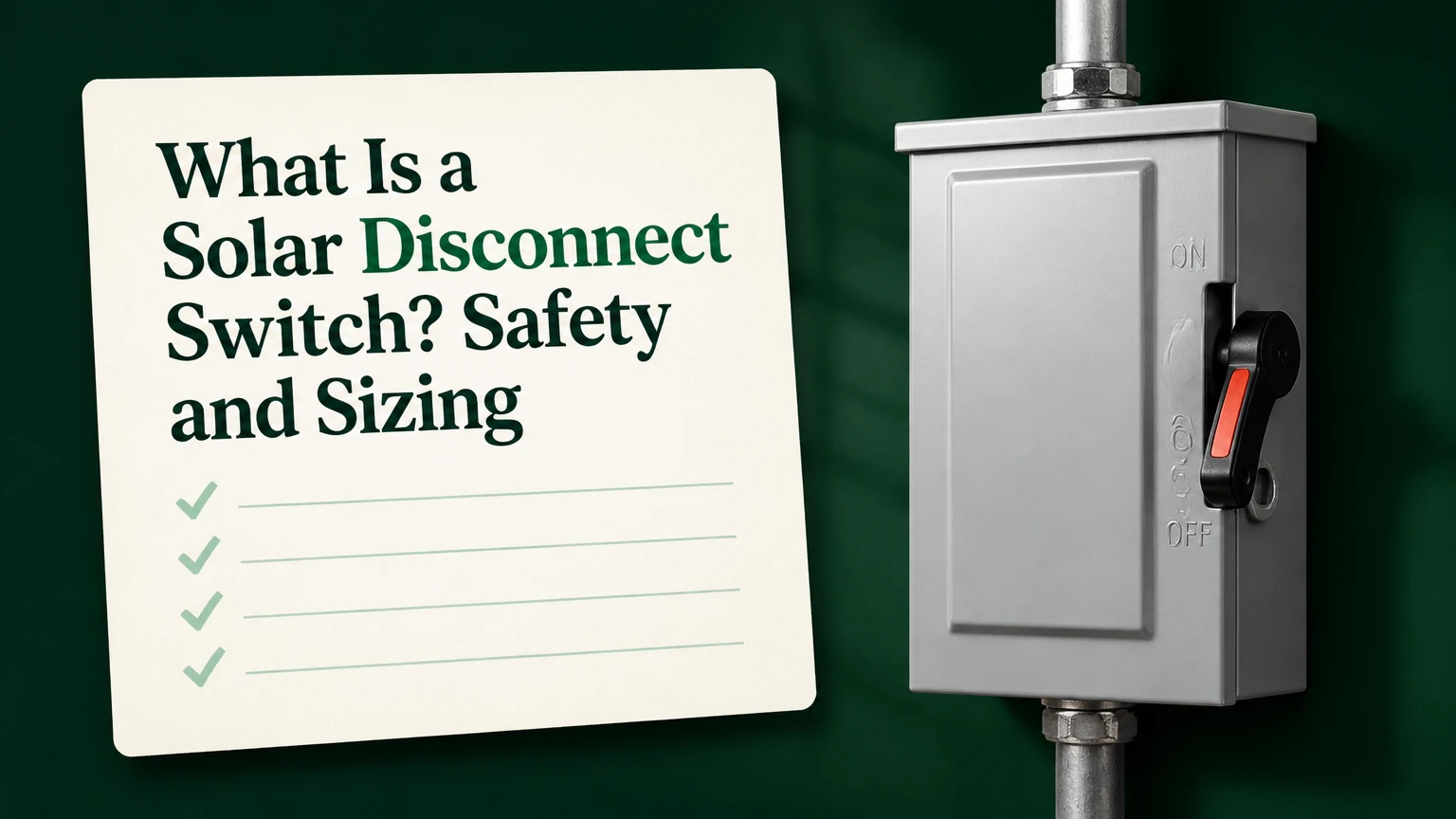
A solar disconnect switch is a manually operated device that separates part of a photovoltaic system from another part, creating an intentional isolation point for service or emergency access. Also called a PV disconnect, DC isolator, or PV switch-disconnector, it may interrupt solar-panel output, inverter output, or both, depending on its location and rating.
Key facts at a glance
A PV disconnect isolates conductors; a circuit breaker also provides overcurrent protection when properly rated.
A DC-rated switch is required for photovoltaic direct-current circuits because DC arcs do not naturally cross zero.
Turning off an AC disconnect does not de-energize rooftop panels or the DC input of a string inverter.
A typical residential PV disconnect is rated around 600-1,000 VDC and 16-63 A, but the design determines the correct value.
The disconnect must be listed for its voltage, current, pole configuration, enclosure environment, and interrupting duty.
An open handle does not prove that every conductor is voltage-free; upstream PV, batteries, generators, and utility sources can remain energized.
What Does a Solar Disconnect Switch Do?
A solar disconnect switch provides a visible, manually controlled break between selected sections of a solar-electric installation. The primary purpose is safe isolation, allowing a qualified person, utility worker, inspector, or emergency responder to separate an inverter, combiner, battery, or building wiring from an energy source.
The device does not automatically detect a fault. A non-fused disconnect does not protect cable against excessive current, and opening the switch does not extinguish sunlight-driven voltage on conductors that remain connected to the modules. Those limitations make location and labeling as important as the switch itself.
In a grid-tied system, the installation may contain a rooftop array disconnect, inverter DC disconnect, inverter AC disconnect, service equipment, and utility-required accessible disconnecting means. One handle may isolate only one portion. The one-line diagram identifies the exact boundary.
Disconnect, breaker, isolator, and rapid shutdown
These terms overlap in casual conversation but describe different functions.
| Device | Primary function | Typical PV location | Overcurrent function |
|---|---|---|---|
| Non-fused disconnect | Manual conductor isolation | Array or inverter | None |
| Fused disconnect | Isolation plus fuse protection | Combiner or feeder | Cartridge fuses |
| Circuit breaker | Switching and overcurrent interruption | AC panel or combiner | Thermal-magnetic or electronic |
| Rapid-shutdown equipment | Reduces hazardous voltage in defined PV boundary | Module or array boundary | Not ordinary branch protection |
| Service disconnect | Separates premises wiring from utility supply | Main service equipment | Depends on equipment design |
A disconnect can be switch-rated and load-break rated without being a circuit breaker. Conversely, a breaker may function as a disconnect only when its listing, handle, accessibility, and installation satisfy the applicable electrical rules.
How Does a PV Disconnect Work?
A solar disconnect opens mechanical contacts and holds them apart with insulation and an air gap. On a DC circuit, a spring-assisted mechanism separates contacts quickly while arc barriers, magnetic blowout features, or arc chutes lengthen and cool the arc until current stops.
Alternating current passes through zero many times each second. At 60 hertz, the waveform crosses zero 120 times per second, which helps an AC arc collapse when contacts separate. Photovoltaic DC has no equivalent natural zero crossing, so an AC-only switch can sustain an arc long enough to damage the enclosure or start a fire.
The three electrical states
- Closed or ON: The contacts connect the source and load, and the circuit carries current.
- Open or OFF: The contacts separate and the switch provides the specified isolation distance.
- Open and locked: The handle is secured against re-energization during authorized work.
A switch marked OFF is not a voltage tester. PV modules produce voltage whenever sufficient light reaches them, and a battery inverter can backfeed conductors from a second direction. Safe work requires an approved procedure, lockout and tagout where applicable, and test equipment rated for the system.
One practical rule matters more than the handle position: never assume a downstream terminal is dead until a qualified person proves absence of voltage using a properly rated meter and a known-live, test, known-live sequence.
Where Is a Solar Disconnect Installed?
A solar disconnect is installed at a designed boundary between an energy source and equipment that may need isolation. Common positions include between PV strings and a combiner, between a combiner and a string inverter, at an inverter’s DC input, or between the inverter’s AC output and the premises panel.
The correct location depends on the National Electrical Code edition adopted locally, the authority having jurisdiction, the utility interconnection agreement, the inverter listing, conductor routing, and emergency-access requirements. In the United States, NEC 690.13 addresses PV system disconnecting means, while NEC 690.12 addresses rapid shutdown.
Common residential arrangement
| System section | Device commonly used | Typical voltage | Main purpose |
|---|---|---|---|
| Roof array to combiner | String fuse or DC isolator | 300-600 VDC | String protection and isolation |
| Combiner to inverter | Fused or non-fused DC disconnect | 600-1,000 VDC | Feeder isolation |
| Inverter to load center | AC disconnect or breaker | 120/240 VAC | Inverter output isolation |
| Service or meter interface | Utility-approved disconnect | 120/240 VAC | Utility and service access |
| Battery inverter circuit | DC fuse, breaker, or disconnect | 48-600 VDC | Battery and inverter isolation |
A utility-accessible AC disconnect may be required outside a building, but the utility’s rule does not automatically replace the DC isolation required for the PV source. A switch hidden behind a locked gate, inside an inaccessible crawlspace, or where a responder cannot reach it may fail practical accessibility requirements even if the equipment itself is correctly rated.
What Types of Solar Disconnects Are Available?
The main choices are DC or AC, integrated or external, fused or non-fused, and indoor or environmental-rated. Selection follows the circuit’s electrical characteristics, not the panel wattage alone.
| Type | Electrical duty | Typical rating range | Best application |
|---|---|---|---|
| DC PV isolator | Continuous photovoltaic DC | 600-1,500 VDC, 16-250 A | Array and inverter isolation |
| AC disconnect | Utility-frequency AC | 120/240 VAC, 30-200 A | Inverter output and grid interface |
| Inverter-integrated switch | Manufacturer-defined DC or AC duty | 600-1,000 VDC commonly | Compact string-inverter installations |
| Fused disconnect | Isolation and replaceable fuse protection | 600-1,500 VDC, 15-400 A | Combiner and commercial feeders |
| Non-fused disconnect | Mechanical isolation only | 600-1,500 VDC, 16-250 A | Circuits protected elsewhere |
DC versus AC disconnects
A DC disconnect isolates the array side of an inverter. It can prevent the inverter from receiving current through the disconnected circuit, but the roof wiring upstream of the switch can remain energized in daylight.
An AC disconnect isolates the inverter from the building panel or utility grid. It does not turn off the modules, the DC conductors, or the inverter’s DC terminals. A grid-tied inverter may shut down after losing the grid, but shutdown is not the same as physical isolation.
Fused versus non-fused models
A fused disconnect combines a switch with fuse holders. Fuses can protect conductors against short-circuit or overcurrent conditions when the fuse type, voltage, interrupt rating, and system calculation are correct. They also create replacement cost and require the correct spare fuse.
A non-fused model is simpler and often smaller. It requires separate overcurrent protection, such as string fuses, a feeder breaker, or an upstream listed protective device. It is not a substitute for that protection.
Integrated versus external switches
An inverter-integrated disconnect saves wall space and can reduce conduit work. Its limitation is serviceability: a failed internal mechanism may require manufacturer-specific repair or inverter replacement, and the handle may not provide the external emergency access that a utility or inspector expects.
External disconnects cost more in materials and labor but create a clear, serviceable isolation point. For outdoor equipment, select a listed enclosure rather than placing an indoor switch beneath an improvised weather cover.
How Do You Size a Solar Disconnect?
A solar disconnect must be rated for the circuit’s maximum voltage, calculated current, number of poles, polarity, load-breaking duty, short-circuit environment, and enclosure conditions. The voltage calculation must account for the coldest design temperature because module open-circuit voltage rises as temperature falls.
For a typical string, designers calculate corrected maximum open-circuit voltage from the module or string data and the applicable temperature coefficient. The switch’s maximum DC voltage must equal or exceed that result. A 600 VDC switch is not automatically adequate for a string that can exceed 600 V during a cold morning.
Current sizing requires more care than applying a universal number to the switch label. NEC calculations commonly use 125% of PV short-circuit current for continuous output and may require additional adjustments for conductor ampacity, temperature, grouping, and equipment limitations. The final disconnect rating must meet the calculated circuit ampacity and the manufacturer’s instructions.
| Design item | Typical residential value | Commercial example | Selection check |
|---|---|---|---|
| String open-circuit voltage | 400-550 VDC | 900-1,500 VDC | Apply cold-temperature correction |
| Circuit current | 10-15 A Isc | 15-40 A Isc per string | Use array and string configuration |
| Disconnect current rating | 16-63 A | 100-250 A or higher | Meet calculated ampacity |
| DC voltage rating | 600-1,000 VDC | 1,000-1,500 VDC | Must exceed maximum corrected voltage |
| Poles | 2-4 poles | 2-8 poles | Follow grounded and ungrounded conductor design |
| Interrupt duty | Manufacturer-listed | Equipment-specific | Confirm available fault current |
The often-repeated 1.56 multiplier, calculated as 1.25 multiplied by 1.25, is not a universal instruction to buy a 156%-rated disconnect. It relates to particular conductor and overcurrent-protection calculations. The project engineer or licensed electrician must apply the adopted code and equipment instructions.
What other markings matter?
Look for a recognized listing, such as UL 98, UL 98B, UL 1741-related inverter equipment, or the applicable IEC certification for the installation market. The exact listing must match the product category and jurisdiction.
Check for DC polarity and direction markings. Some switches use magnetic arc-control geometry that depends on current direction. Reverse wiring can reduce arc-control performance during load breaking.
Can You Turn Off Solar Panels With a Disconnect?
A conventional solar disconnect cannot make illuminated panels produce zero voltage. It can isolate the panel circuit from an inverter or downstream conductor, but the module-side conductors between the array and the open contacts may remain energized.
Rapid-shutdown equipment addresses a different hazard. Under NEC 690.12, compliant systems reduce voltage within the defined rapid-shutdown boundary according to the adopted requirements, equipment listing, and system design. Operating a manual disconnect may initiate rapid shutdown in some systems, but that behavior is not universal.
A rooftop array with module-level power electronics, a string inverter with listed rapid shutdown, and an older string-only system can respond differently. Read the placard, one-line diagram, inverter manual, and rapid-shutdown instructions before treating one handle as a complete emergency solution.
How Do You Operate a Solar Disconnect Safely?
Only trained and authorized people should operate or service energized PV equipment. A typical shutdown sequence is to follow the manufacturer’s instructions, reduce or remove AC output where directed, open the specified disconnect with one deliberate motion, apply lockout and tagout when work follows, and verify every relevant source before contact.
A safe operating sequence
- Identify every source. Account for utility AC, PV DC, batteries, generators, capacitors, and alternate inverter feeds.
- Read the system placard. Follow the equipment-specific shutdown order instead of assuming all systems use the same sequence.
- Reduce load where instructed. Opening a properly listed load-break switch is permitted by its rating, but removing inverter output first can reduce contact wear.
- Operate the handle decisively. Do not slowly move a rotary handle through an energized position.
- Lock and tag the open device. Prevent another person from restoring power while work is underway.
- Test for absence of voltage. Test source and load conductors with an appropriately rated meter, then confirm the meter still works.
The final step is non-negotiable. A disconnected inverter can still receive voltage from a second string, battery, AC backfeed, or stored energy component.
Solar Disconnect Costs and Installation Time
A typical residential disconnect component costs $75-$200, while heavy commercial fused equipment commonly costs $300-$1,500 or more. A retrofit often takes 1.5-3 hours and may cost $150-$400 in labor before permits, conduit complexity, roof access, engineering, or utility fees.
| Project type | Equipment cost | Typical labor | Typical duration |
|---|---|---|---|
| Residential AC disconnect | $75-$180 | $150-$300 | 1-2 hours |
| Residential DC isolator | $90-$250 | $200-$400 | 1.5-3 hours |
| Fused combiner disconnect | $150-$500 | $250-$600 | 2-4 hours |
| Commercial 100-250 A switch | $300-$1,500+ | $500-$2,000+ | 3-8 hours |
| Battery isolation retrofit | $150-$800 | $300-$1,000 | 2-5 hours |
These are typical planning ranges, not a quotation. Trenching, conduit replacement, an inaccessible attic, rapid-shutdown upgrades, and utility inspection can change the total substantially.
Solar Disconnects Compared With Alternatives
The best isolation method depends on the source being controlled. An AC breaker may isolate inverter output, while a DC isolator controls PV input, and a battery fuse-disconnect controls stored energy that sunlight cannot disable.
| Option | Source controlled | Typical cost | Main limitation |
|---|---|---|---|
| AC breaker | Inverter output or branch circuit | $20-$150 | Leaves PV DC energized |
| AC disconnect | Inverter to panel or grid | $75-$250 | Does not isolate rooftop conductors |
| DC isolator | Array to inverter | $75-$300 | Does not remove module voltage upstream |
| Fused DC disconnect | Array feeder with protection | $150-$800 | Fuse replacement required |
| Rapid-shutdown system | Module or array boundary | $200-$1,500+ system cost | Requires compatible equipment |
| Battery disconnect | Battery to inverter/load | $100-$1,000 | PV and utility sources may remain live |
A breaker is the practical choice when overcurrent protection and switching are both required on a properly designed AC circuit. A dedicated PV disconnect is the better choice when the system needs a clearly identified, external, manually operated isolation point on the DC side.
Common Mistakes and Edge Cases
Using an AC-only switch on a DC circuit
An AC-rated switch may lack the contact spacing and arc-control system needed for PV DC. Use a switch with a marked DC voltage and current rating that covers the circuit, not a product whose label only says 120 or 240 VAC.
Assuming OFF means zero volts
The source side of a disconnect can remain energized from solar modules. A second source can energize the load side. Test each conductor and do not rely on the handle, an inverter display, or a dark screen.
Ignoring cold-weather voltage
Module voltage increases as temperature decreases. A string that measures safely below 600 V in warm weather can exceed a 600 V equipment limit in a cold climate if the temperature coefficient and string length were not calculated.
Reversing polarity or line and load
Many DC isolators specify source and load terminals. Follow those markings because the internal arc-control path may be directional. A wiring error can appear harmless during normal operation and become dangerous when the switch opens under load.
Treating a disconnect as overcurrent protection
A non-fused isolator cannot clear a conductor short circuit. Confirm where string fuses, feeder breakers, and battery protection are located before removing any protective device from a design.
Selecting the wrong enclosure
| Environment | Suitable enclosure example | Typical concern |
|---|---|---|
| Indoor dry utility room | NEMA 1 | Dust and moisture are limited |
| Outdoor residential wall | NEMA 3R or IP65 equivalent | Rain, snow, and condensation |
| Coastal installation | NEMA 4X | Salt corrosion and UV exposure |
| Agricultural or washdown area | NEMA 4X or listed washdown enclosure | Chemicals, water jets, ammonia |
| High-temperature rooftop | Manufacturer-rated outdoor enclosure | Derating and seal aging |
NEMA and IP classifications are not interchangeable by number alone. Confirm the product’s actual listing, UV resistance, temperature range, cable-entry method, and corrosion rating.
Why Is a Solar Disconnect Hot, Noisy, or Stiff?
Heat, buzzing, hissing, or a seized handle indicates a condition that deserves prompt inspection rather than continued operation. Common causes include loose terminations, undersized equipment, corroded contacts, water intrusion, incompatible wire, or contact damage from repeated load breaking.
| Symptom | Likely cause | Safe response | Replacement clue |
|---|---|---|---|
| Hot enclosure | Loose lug or overloaded switch | Qualified inspection and torque check | Heat remains after correction |
| Buzzing or hissing | Arcing or vibrating contact | De-energize according to procedure | Discoloration or pitting |
| Stiff handle | Corrosion or broken mechanism | Do not force the handle | Incomplete contact movement |
| Tripping fuse | Fault or undersized fuse | Locate fault before replacement | Repeated operation |
| Water inside box | Failed gasket or conduit seal | Isolate and inspect enclosure | Rust or insulation damage |
A thermal camera can locate abnormal temperature differences, but it cannot prove that a circuit is safe to touch. Manufacturer torque values, conductor preparation, and enclosure sealing must be checked by a qualified person.
A useful field rule is to treat repeated warmth as a connection problem until proven otherwise. Replacing a larger switch without finding the loose termination can leave the real hazard in place.
Buying Checklist for a PV Disconnect
Choose the disconnect only after confirming the system’s electrical design and local requirements. A product page that lists amperage but omits DC load-breaking duty, polarity, listing, and enclosure data is incomplete for a PV application.
Check these items:
- Circuit type: PV DC, inverter AC, battery DC, or service interface.
- Maximum corrected voltage: Include cold-temperature module voltage.
- Continuous current and calculated ampacity: Use the design calculation, not panel wattage alone.
- Poles and switching arrangement: Confirm which conductors must open.
- DC load-break rating: Verify the rating at the actual voltage and current.
- Fuse compatibility: Match fuse class, size, interrupt rating, and manufacturer approval.
- Short-circuit and interrupt rating: Compare with available fault current.
- Direction and polarity: Follow source, load, positive, and negative markings.
- Enclosure: Match indoor, outdoor, UV, corrosion, and washdown conditions.
- Accessibility and labeling: Coordinate with the one-line diagram, placards, inspector, and utility.
For a small off-grid system, a listed combiner box with string fuses and an integrated DC disconnect can reduce wiring errors. For a commercial array, engineered switchgear with visible isolation, selective coordination, and maintenance access usually justifies its higher cost.
Frequently Asked Questions
Is a solar disconnect switch required?
A solar disconnect is commonly required for PV installations, but the exact quantity, location, and accessibility depend on the adopted electrical code, system architecture, utility rules, and authority having jurisdiction. A licensed installer should confirm whether the design needs separate AC, DC, battery, and service disconnecting means.
Can I install a solar disconnect myself?
A homeowner may be allowed to install equipment in some jurisdictions, but PV disconnect work involves shock, arc-flash, backfeed, fire, permitting, and utility-interconnection risks. A qualified electrician should perform or supervise conductor termination, torque verification, testing, labeling, and inspection, especially on systems above ordinary low-voltage battery levels.
Is a PV isolator the same as a solar disconnect?
PV isolator and solar disconnect usually refer to the same general isolation function. Regional terminology differs: IEC-oriented markets often use isolator or switch-disconnector, while North American documentation more often uses PV disconnecting means. The product’s rating and listing matter more than the name.
Does a solar disconnect stop battery power?
A PV disconnect stops only the circuit it opens. It does not stop battery current unless the battery circuit has its own properly rated fuse, breaker, or disconnect. Hybrid inverters require a shutdown procedure that addresses PV, battery, AC grid, and backup-load sources separately.
How often should a solar disconnect be inspected?
Inspect the enclosure, labels, handle, conduit entries, corrosion, and signs of heating during scheduled system maintenance, often annually for residential systems and more frequently in coastal, agricultural, or commercial environments. Do not open energized equipment unless you are qualified and following the manufacturer’s procedure.
The Bottom Line
A solar disconnect switch is a manually operated isolation device for a defined portion of a photovoltaic system. The correct device must match DC or AC duty, maximum corrected voltage, calculated current, poles, polarity, interrupt conditions, enclosure environment, and local accessibility rules.
The most important distinction is scope: an AC disconnect does not de-energize rooftop PV, a non-fused disconnect does not provide overcurrent protection, and an OFF handle does not prove zero voltage. For that reason, system diagrams, rapid-shutdown equipment, battery isolation, qualified testing, and local code review must accompany the switch itself. A properly selected solar disconnect switch makes service safer because it creates a known isolation boundary, not because it magically removes every source of electrical energy.