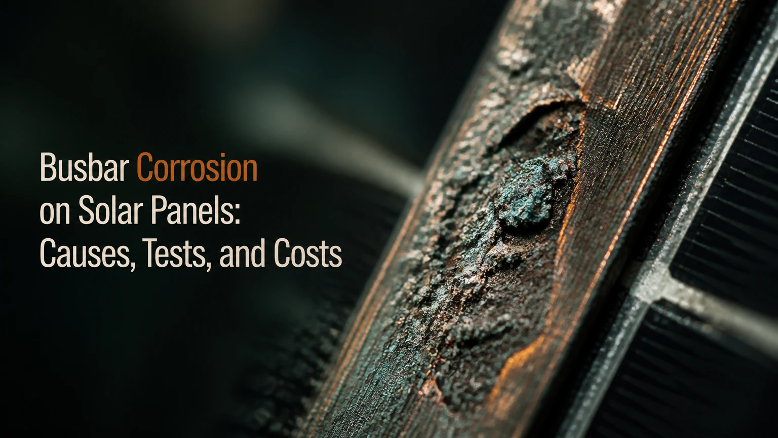
Busbar corrosion on solar panels is electrochemical damage to the conductive metallization and interconnects that collect and carry cell current. Moisture, oxygen, contaminants, dissimilar metals, and sometimes acids released by hydrolyzing EVA encapsulant can increase contact resistance, create localized heating, interrupt current paths, and eventually reduce module output or compromise safety.
Key Facts at a Glance
- Busbars collect current from cell fingers and transfer it through ribbons or wires toward the junction box.
- Moisture ingress is the enabling condition for most internal corrosion, but visible discoloration alone does not prove busbar corrosion.
- EVA can release acetic acid during hydrolysis; POE generally reduces that acid-related risk, but no encapsulant makes poor manufacturing or damaged seals harmless.
- A corroded internal busbar normally cannot be cleaned or repaired without destroying the laminate, so module replacement is the usual remedy.
- Infrared thermography locates abnormal heating, while electroluminescence reveals inactive areas, cracks, and interrupted current paths.
- Typical single-module replacement costs range from about $300-$600 for many residential systems, but local labor, access, shipping, and electrical redesign can change the total substantially.
What Is Busbar Corrosion on Solar Panels?
Busbar corrosion on solar panels is the oxidation, chemical attack, or galvanic degradation of current-collecting metal inside a photovoltaic module. The affected parts can include silver or silver-aluminum cell busbars, tinned copper ribbons, solder joints, wire interconnects, and contact interfaces near the cell edges.
A solar cell’s narrow fingers collect carriers across the cell surface. Fingers connect to wider busbars, and busbars connect to ribbons, wires, or overlapping cell joints that move current through the module circuit. A defect in one busbar segment may increase resistance locally, while a severed path can force current through parallel routes or bypass diodes.
The internal metal network is protected by glass, encapsulant, a backsheet or second glass layer, and perimeter sealing. Corrosion therefore usually indicates a moisture-control, materials, manufacturing, handling, or installation problem rather than ordinary surface dirt.
Which failures resemble busbar corrosion?
Snail trails, delamination, cell cracks, solder fatigue, junction-box faults, connector heating, and frame corrosion can produce similar output symptoms. A dark line across a cell is evidence for investigation, not a diagnosis.
| Visible or electrical symptom | Possible cause | Confirming method |
|---|---|---|
| Brown or gray lines near cracks | Moisture-related discoloration or snail trails | EL imaging plus close visual inspection |
| Bright cell or ribbon hotspot | High-resistance solder joint, crack, or connector | IR scan under load and electrical isolation |
| Lower string voltage | Open circuit, bypassed cell group, or interconnect break | String voltage test and IV curve |
| Hazy white laminate | Delamination or moisture pathway | Visual inspection and insulation testing |
| Corroded frame or lug | External galvanic or atmospheric corrosion | Torque, continuity, and metal-interface inspection |
How Does Corrosion Develop Inside a Solar Module?
Internal solar-module corrosion develops when moisture reaches conductive materials and combines with oxygen, ionic contaminants, heat, or reactive chemicals. The sequence commonly begins with laminate damage or permeability, continues through chemical and electrochemical reactions, and ends with resistance growth, current interruption, or localized heating.
The corrosion sequence
- A moisture barrier weakens. UV exposure, thermal cycling, hail, wind flexing, poor edge sealing, delamination, or manufacturing defects can create a pathway.
- Water vapor or liquid water reaches the laminate. Moisture can enter through edges, damaged backsheets, junction-box interfaces, cracks, or permeable polymer layers.
- The local chemistry changes. Hydrolyzed EVA may release acetic acid, while salt, sulfur compounds, and other contaminants increase ionic conductivity.
- Protective plating or contact surfaces degrade. Tin, silver, solder, or copper interfaces can oxidize or dissolve under suitable electrochemical conditions.
- The contact resistance rises. Current continues through a smaller or poorer conductive area, increasing resistive loss according to (P=I^2R).
- Heat and mechanical stress accelerate failure. Thermal cycling can enlarge cracks, weaken solder joints, and expand delaminated regions.
EVA acid generation is not automatic proof that a module will corrode. Temperature, moisture concentration, acid transport, metallization chemistry, seal quality, and electrical potential determine whether measurable damage develops.
What role do EVA and POE play?
EVA is widely used because it is economical, processable, and optically suitable, but hydrolysis can produce acetic acid under heat and moisture. POE has lower water-vapor transmission and does not generate acetic acid through the same hydrolysis pathway, although POE modules still depend on sound lamination, edge seals, glass quality, and junction-box adhesion.
Dual-glass construction removes the polymer backsheet and can improve moisture resistance, but the heavier module requires compatible rails, clamps, and structural loading calculations. A glass-glass module can still suffer cell cracks, solder fatigue, junction-box defects, or edge-seal failure.
Which Conditions Cause Busbar Corrosion?
The main conditions are sustained humidity, liquid-water exposure, chloride deposition, acidic contaminants, thermal cycling, and mechanical damage that opens a route into the laminate. Climate raises or lowers risk, but manufacturing quality and installation handling often determine whether environmental stress becomes a field failure.
| Corrosion driver | Typical exposure | Internal consequence | Practical control |
|---|---|---|---|
| Coastal chloride | Salt aerosol within several kilometers of shore, distance varies with wind | Faster oxidation and conductive contamination | Salt-tolerant module, compatible metals, scheduled inspection |
| Tropical humidity | Relative humidity frequently above 80% | Higher moisture diffusion and condensation risk | POE or tested EVA design, drainage, edge inspection |
| Industrial sulfur | SO₂ and particulate pollution near factories | Sulfide or oxide attack on contacts | Site-specific material review and frequent thermography |
| Thermal cycling | Large daily temperature swings or hot roofs | Expansion mismatch, solder fatigue, seal stress | Correct clamping and modules qualified for site conditions |
| Hail or rough handling | Cell cracks and laminate impact damage | Moisture channels and isolated cell regions | Packaging controls, EL acceptance testing |
| Standing water | Debris-blocked frame channels or low mounting angle | Prolonged edge and backsheet wetting | Clear drainage paths and manufacturer slope guidance |
The often-repeated “within 5 km of the sea” rule is only a screening shortcut. Wind direction, elevation, salt concentration, rainfall, vegetation, roof geometry, and washing frequency can make a site farther inland more aggressive than a sheltered coastal site.
Agricultural ammonia and alkaline dust also deserve attention. These contaminants may not create the same chemistry as acetic acid, but they can attack exposed metals, frames, coatings, and connectors when moisture forms an electrolyte.
Which Module Designs Reduce Corrosion Risk?
POE encapsulant, dual-glass construction, robust edge seals, and redundant multi-wire interconnection generally reduce moisture-related failure exposure, but they do not guarantee immunity. Design selection should match the site’s humidity, salt, mechanical loading, service access, and warranty requirements.
| Module architecture | Typical interconnection | Moisture strategy | Main trade-off |
|---|---|---|---|
| 5BB or 9BB EVA-backsheet | 5 or 9 flat busbars | Standard glass-polymer laminate | Lower cost, fewer parallel current paths |
| 10BB-16BB MBB | Multiple wires or narrower busbars | More redundant collection paths | More solder or bonding interfaces |
| Shingled | Overlapping cell strips with conductive adhesive | Fewer conventional busbars | Difficult field repair and adhesive-process dependence |
| SmartWire or wire-based | Dense wire matrix | Reduced reliance on wide flat busbars | Specialized manufacturing and service limits |
| N-type TOPCon or HJT glass-glass | MBB, wire, or proprietary contacts | Often paired with POE and second glass | Higher weight and possible racking changes |
MBB modules can limit the electrical effect of a single crack because current has more parallel routes. They do not prevent corrosion at a shared solder joint, ribbon termination, junction box, or laminate edge.
Busbar count is therefore a weak standalone buying criterion. Encapsulant specification, damp-heat test evidence, product warranty language, factory electroluminescence records, and the manufacturer’s local service history carry more decision value.
Is dual-glass POE always the best choice?
Dual-glass POE is usually the stronger risk-reduction choice for humid, coastal, or high-value installations when the racking system supports its weight. It is not automatically the best choice for every roof because extra mass, rear-side access, transport handling, and clamp compatibility can raise installation complexity.
IEC 61215 qualification and IEC 61730 safety qualification are useful baseline requirements, not guarantees of a 25-year field life. Ask for the exact module bill of materials, humidity-freeze and damp-heat test information, permitted mounting configurations, and warranty exclusions for salt, ammonia, or improper handling.
How Much Output Can Corrosion Cost?
Corrosion-related losses range from negligible localized resistance to severe string underperformance, and no universal annual percentage applies. Normal module degradation is often specified around 0.3%-0.5% per year for many current products, whereas an active defect can cause a sudden step loss, hotspot, bypass-diode activation, or complete circuit interruption.
A string may lose more energy than the visibly damaged module suggests. In a series-connected array, the weakest module or a bypassed cell group can constrain current, while inverter maximum-power tracking and parallel strings alter the measured system effect.
| Condition | Typical observed pattern | Energy implication | Decision threshold |
|---|---|---|---|
| Early discoloration without electrical anomaly | Normal IV curve and no hotspot | Usually unquantified or minor | Document and monitor |
| Localized resistance increase | One hotspot under load | Approx. 1%-10% module loss is possible | Confirm with IV and thermal data |
| Bypassed cell group | Step in IV curve, lower operating voltage | Often 1/3 module voltage-group loss | Warranty assessment |
| Open interconnect | String voltage or current interruption | Module or string may produce near-zero output | Isolate and replace |
| Active hotspot with backsheet damage | Bright thermal anomaly | Accelerating loss and safety risk | Shut down affected circuit if safe |
These ranges are practitioner-oriented screening ranges, not guarantees. Temperature, irradiance, inverter clipping, soiling, shading, mismatch, sensor error, and seasonal weather must be removed before assigning loss to corrosion.
How Do You Diagnose Internal Busbar Damage?
Internal busbar damage requires correlated evidence from visual inspection, electrical testing, thermal imaging, and, when necessary, electroluminescence. A single photograph, low production day, or warm cell does not identify the corrosion mechanism reliably.
Use a staged diagnostic workflow
1. Review operating data first. Compare inverter MPPT voltage and current by string, normalized to irradiance and module temperature. A persistent divergence is more meaningful than a one-day production dip.
2. Inspect without opening the module. Look for delamination, bubbles, moisture haze, backsheet cracks, discoloration, damaged junction boxes, burnt connectors, and frame drainage problems. Do not remove glass or cut the laminate.
3. Perform an IV-curve test. An IV tracer can identify reduced fill factor, current loss, voltage-group bypassing, abnormal series resistance, and mismatch. Test at a documented irradiance and temperature, then compare with adjacent modules.
4. Scan thermally under load. Use an infrared camera during strong sunlight, ideally above roughly 600 W/m² with stable loading and appropriate emissivity settings. A bright line or point can indicate resistance, but shadows, loose connectors, bypass diodes, and soiling can produce similar patterns.
5. Commission EL imaging. EL testing in darkness can expose microcracks, inactive cell regions, interrupted fingers, and solder discontinuities. EL cannot chemically identify copper oxide or acetic-acid corrosion by itself.
6. Test insulation resistance when safety evidence warrants it. A qualified technician can use an insulation-resistance tester according to the module and system manufacturer’s procedure. Low resistance indicates dielectric or moisture-related leakage, not specifically busbar corrosion.
| Test | Best detection target | Useful output | Main limitation |
|---|---|---|---|
| Visual inspection | Delamination, cracks, staining, connector damage | Photographic defect record | Internal corrosion can remain invisible |
| IV curve | Series resistance, bypassing, mismatch | Fill factor, voltage, current curve | Requires stable irradiance and temperature |
| IR thermography | Hotspots and resistive heating | Thermal image with location | Cannot identify chemistry alone |
| EL imaging | Cracks, inactive areas, broken contacts | Dark-cell and crack map | Usually requires specialist equipment |
| Insulation resistance | Leakage and dielectric weakness | Resistance value at test voltage | Does not prove busbar corrosion |
An independent laboratory may use microscopy, cross-sectioning, ion chromatography, or chemical analysis, but destructive analysis usually makes sense only for warranty disputes, fleet-level failure studies, or safety investigations.
Can Corroded Solar Busbars Be Repaired?
A corroded busbar sealed inside a laminated module is generally not economically or reliably repairable in the field. Cleaning the exposed glass does not remove internal corrosion, and cutting into the laminate can destroy insulation, invalidate certification, create new moisture paths, and void the product warranty.
Technicians can sometimes repair external connectors, replace a junction box under approved procedures, or correct a loose cable and mounting fault. Those actions address adjacent failures, not corrosion embedded in the cell laminate.
| Remedy | Suitable defect | Typical residential cost | Expected result |
|---|---|---|---|
| Glass cleaning | Surface dirt or salt film | $10-$40 per module allocation | Restores optical transmission only |
| Connector replacement | Heat-damaged compatible connector | $75-$200 | Corrects external connection fault |
| Junction-box replacement | Detached or failed box, approved process | $150-$350 | Restores box function if laminate is sound |
| Single-module replacement | Internal corrosion or open interconnect | $300-$600 typical | Restores design output if matched |
| Commercial module replacement | Internal module failure at scale | $250-$900 per module, site-dependent | Includes logistics and access variation |
The replacement module must match electrical characteristics, dimensions, connector family, mounting zones, and fire and racking requirements. Mixing a significantly different current class in a series string can increase mismatch even when the nameplate wattage appears similar.
What Should Owners Do About a Suspected Defect?
Owners should document the defect, preserve operating data, obtain an independent diagnosis, and contact the installer and manufacturer before authorizing module disassembly. Warranty timelines often depend on serial numbers, photographs, commissioning records, test reports, and proof that the system followed installation instructions.
Residential response
Record the module serial number, installation date, inverter string data, defect photographs, weather conditions, and any thermal or EL report. Avoid applying sealant, conductive paste, paint, or adhesive to the module laminate because those substances can conceal the defect and complicate a warranty inspection.
Commercial and utility response
Use normalized fleet analytics to identify outliers, then prioritize IV and drone thermography by risk. A practical inspection cycle is annual for stable inland arrays and more frequent after severe storms or where coastal corrosion, industrial pollution, or repeated connector heating is documented.
DIY and off-grid response
Do not disconnect energized PV connectors, open junction boxes, or perform insulation tests without appropriate training and equipment. A module can generate hazardous DC voltage even when an inverter is off, and arc faults can persist where AC isolation has already occurred.
What Are the Typical Costs and Timeframes?
A residential technician can often complete visual and electrical triage in 1-3 hours, while EL imaging or a commercial drone survey may require a specialist visit. Module replacement commonly takes 30-90 minutes per accessible module, but steep roofs, battery-backed systems, shipping, crane access, and string redesign can extend the work.
| Service or event | Typical timeframe | Typical cost | Variables |
|---|---|---|---|
| Remote production review | 30-60 minutes | $0-$150 | Monitoring access and data quality |
| On-site visual and electrical inspection | 1-3 hours | $150-$500 | Travel, roof access, test equipment |
| EL inspection | 1-4 hours | $250-$1,000 | Number of modules and dark-site setup |
| Drone IR survey | 1 day including report | $500-$2,500 | Array size, aviation rules, reporting |
| One residential module replacement | 30-90 minutes | $300-$600 typical | Module availability and roof difficulty |
| Commercial corrective campaign | 1-10 working days | $5,000-$100,000+ | Fleet size, access, logistics, downtime |
Costs are typical planning figures rather than guaranteed market prices. Warranty replacement may reduce the module charge while leaving labor, freight, disposal, testing, or roof-access costs payable by the owner.
Which Prevention Rules Matter Most?
The strongest prevention measures are quality-controlled module procurement, careful transport, correct mounting, compatible external metals, clear drainage, and inspection after severe weather. Preventing moisture pathways is more effective than trying to treat corrosion after the laminate has failed.
Use the following field rules:
- Preserve the laminate. Never step on modules, lift them by cables, drag them across racks, or stack them without the manufacturer’s packaging method.
- Follow clamp zones and torque. Use a calibrated torque wrench and the module installation manual. Over-tightening can stress glass; under-tightening permits movement.
- Protect drainage. Keep frame channels and roof clearance free of leaves, bird nesting material, and sealant that traps water.
- Match metals and connectors. Use listed connectors from compatible families and approved lugs, washers, coatings, and grounding hardware.
- Inspect after hail and transport incidents. Hidden cell cracks may precede later delamination or contact failure.
- Specify the climate. Request salt-mist, damp-heat, ammonia, or PID-related suitability evidence when the project environment requires it.
One counterintuitive rule matters: washing salt from the glass may improve light transmission while doing nothing for internal corrosion. Surface cleanliness and laminate integrity are separate maintenance problems.
Another practitioner rule is to investigate the inverter and connectors before condemning a busbar. External connector resistance can create a hotter and more dangerous IR signature than an internal metallization defect, while the repair cost and warranty path differ completely.
Which Module Should a Buyer Choose?
For humid or coastal sites, a glass-glass module using POE or another low-moisture encapsulation design is usually the prudent risk choice, provided the racking and roof structure support its weight. For dry inland projects, a well-manufactured EVA-backsheet module can remain a rational value choice when warranty support, handling controls, and installation quality are strong.
| Site situation | Preferred specification | Why it fits | Important qualification |
|---|---|---|---|
| Coastal residential roof | Glass-glass, POE, MBB | Lower moisture and acid-related exposure | Confirm weight and salt warranty terms |
| Tropical commercial array | POE, robust edge seal, documented damp-heat data | Sustained humidity demands better barriers | Schedule thermal and visual inspections |
| Dry inland home | Quality EVA or POE, 9BB-MBB | Lower environmental corrosion pressure | Handling and drainage still matter |
| Industrial facility | POE or tested EVA, contamination review | Pollution can attack contacts and frames | Request site-specific materials guidance |
| Off-grid remote site | Repair-supported, available module format | Logistics and replacement availability dominate | Avoid obscure proprietary sizes |
No module architecture is “corrosion-proof.” Shingled and wire-interconnected products reduce dependence on traditional flat busbars, but adhesives, overlapping joints, ribbons, junction boxes, and cell cracks remain possible failure points.
Frequently Asked Questions
Can cleaning remove busbar corrosion?
Cleaning removes salt, dust, bird residue, and other surface contamination from the front glass, but it cannot remove corrosion sealed inside the laminate. If output remains low after cleaning, compare string data and inspect for hotspots, delamination, connector damage, or cell cracks rather than repeating washes.
Do snail trails prove busbar corrosion?
Snail trails do not prove busbar corrosion. The lines often involve cell cracks, moisture, silver migration, or discoloration around damaged metallization, and some visible trails have little immediate power impact. EL imaging and IV testing are needed to determine whether the pattern includes electrically inactive or high-resistance regions.
How old are panels when corrosion usually appears?
There is no reliable universal age. A poorly sealed or mechanically damaged module in a hot, humid, salty environment can show defects within a few years, while a well-built inland module may operate for decades without meaningful corrosion. Installation records, climate, bill of materials, and defect progression matter more than age alone.
Will solar-panel insurance cover busbar corrosion?
Insurance treatment depends on the policy and cause. Sudden hail or storm damage may receive different consideration from gradual deterioration, manufacturing defects, or excluded maintenance conditions. Preserve the damaged module, obtain an adjuster-approved report, and check whether the product warranty or installer workmanship warranty applies first.
Should a low-producing module be replaced immediately?
Immediate replacement is appropriate when testing confirms an active hotspot, exposed conductors, insulation failure, backsheet burn, or an open interconnect. A visually discolored module with stable electrical performance may be documented and monitored while the owner pursues a warranty decision, provided no safety defect is present.
The Bottom Line
Busbar corrosion on solar panels is an internal electrochemical failure involving moisture, contaminants, metals, encapsulants, and electrical stress. The most dependable response is evidence-based diagnosis: correlate monitoring data with IV testing, thermography, visual inspection, and EL imaging when needed. Internal laminate corrosion is rarely repairable, so climate-appropriate module selection, careful handling, correct drainage, and complete warranty documentation provide the strongest protection against premature replacement.