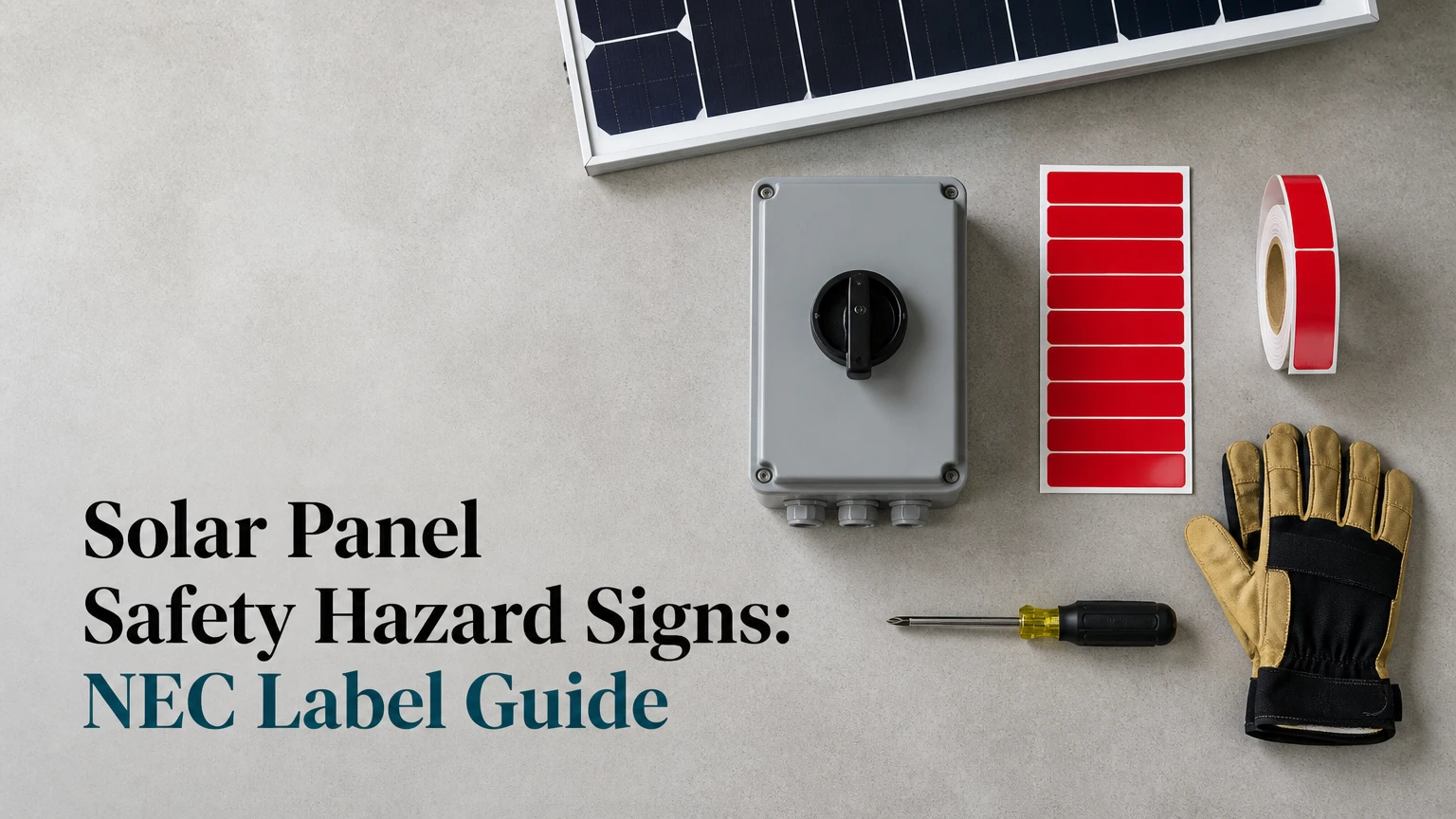
Solar panel safety hazard signs identify photovoltaic circuits, disconnects, rapid shutdown controls, multiple power sources, and associated battery hazards. They help electricians, inspectors, maintenance workers, and emergency responders understand where energy remains present, which equipment isolates it, and what system-specific limits apply, even when utility power is disconnected.
Key Facts at a Glance
Photovoltaic modules can produce voltage whenever sufficient light reaches the modules, even after the utility disconnect opens.
NEC Article 690 commonly governs PV circuit identification, disconnects, rapid shutdown, directories, and warning labels in the United States.
Required wording, placement, color, and data fields vary by NEC edition, local amendments, system type, and the Authority Having Jurisdiction.
A rapid shutdown label identifies the shutdown initiator and the boundary beyond which conductors are reduced to the required voltage.
Battery energy storage systems add separate electrical, thermal, and emergency-response marking obligations.
A label is compliant only when it remains legible, durable, securely attached, and accurate for the installed equipment.
What Are Solar Panel Safety Hazard Signs?
Solar panel safety hazard signs are permanent warnings and identification labels attached to photovoltaic modules’ wiring, disconnects, service equipment, inverters, battery systems, and access points. Their main function is rapid hazard recognition: a responder should be able to identify the PV source, locate isolation equipment, and understand remaining energized areas without relying on installer memory.
Solar PV signage is a passive safety control. It does not de-energize a circuit, replace a disconnect, or make rooftop conductors safe to touch. The signage communicates the system architecture so a trained person can select the correct isolation procedure.
The wording usually comes from the adopted electrical code and equipment requirements. ANSI Z535 provides a framework for signal words, colors, and safety-message design, while ISO 7010 provides standardized graphical symbols used in many international settings. Neither standard automatically determines every PV label location in a U.S. installation.
Why can a solar array remain energized?
A solar array can remain energized because photovoltaic modules generate direct current when illuminated. Opening the utility service disconnect removes one power source, but it does not automatically stop module output or eliminate voltage between energized conductors.
An inverter may stop exporting power, yet DC conductors between the modules and the inverter can remain energized. Rapid shutdown equipment reduces voltage within defined portions of the array when correctly initiated, but the exact safe boundary depends on the equipment listing, wiring method, and adopted NEC rules.
That distinction matters during a structure fire. Firefighters may need to isolate utility, PV, battery, and generator sources separately, then confirm the condition using approved procedures and appropriate personal protective equipment.
Which PV Safety Labels Does a Typical System Need?
A typical grid-connected PV system needs labels for PV circuits, disconnecting means, rapid shutdown initiation, power-source interconnection, equipment directories, and any additional source such as batteries or generators. The exact checklist must be matched to the one-line diagram and the code edition used by the local inspector.
| Label or placard | Typical wording or data | Common location | Main purpose |
|---|---|---|---|
| PV source warning | “WARNING: PHOTOVOLTAIC POWER SOURCE” | DC raceways, enclosures, junction boxes | Identifies conductors connected to PV modules |
| DC disconnect | “SOLAR PV SYSTEM DC DISCONNECT” plus voltage and current data | Exterior of DC disconnect | Identifies the correct isolation device |
| AC disconnect | “SOLAR PV SYSTEM AC DISCONNECT” | PV output disconnect | Separates inverter output from premises wiring |
| Rapid shutdown | “RAPID SHUTDOWN SWITCH FOR SOLAR PV SYSTEM” | Service equipment or designated initiation point | Directs responders to shutdown control |
| PV directory | Source, disconnect, inverter, and conductor information | Service equipment or accessible location | Maps system equipment and sources |
| Dual power source | “WARNING: DUAL POWER SOURCE” | Panelboard or service equipment | Warns that utility and PV sources feed equipment |
| Battery warning | Battery voltage, chemistry, disconnect, and hazard information | ESS enclosure or room entrance | Identifies stored-energy hazards |
| Arc-flash label | Incident energy, boundary, working distance, PPE | Equipment with calculated hazard | Communicates NFPA 70E work controls |
A generic residential kit may contain several of these labels, but a kit is not proof that every supplied label belongs on a particular system. Unused labels can create inaccurate information, which is a safety defect rather than a compliance improvement.
What information belongs on a disconnect label?
A disconnect label should identify the equipment unambiguously and display the electrical values required by the adopted code or equipment instructions. Depending on the installation, that information may include maximum system voltage, maximum circuit current, source type, nominal voltage, and the equipment or circuit controlled.
Use the installed design data, not a product catalog maximum or a copied permit note. The maximum PV source-circuit voltage is calculated from module open-circuit voltage, temperature correction, and series string configuration, while current depends on module ratings, parallel strings, and applicable code adjustment rules.
Where Should Solar PV Labels Be Installed?
Solar PV labels should be installed where a person operating, servicing, inspecting, or responding to an emergency can see them before opening or approaching the associated equipment. NEC placement rules are specific to the label type, so “put labels near the inverter” is not an adequate installation method.
| System location | Labeling action | Typical code context | Inspection checkpoint |
|---|---|---|---|
| DC raceway | Mark the PV source pathway at required intervals | NEC 690.31 and adopted edition | Labels remain visible after supports and insulation are installed |
| Wall or roof penetration | Place identification near the penetration | NEC pathway-marking provisions | Marking is visible from the accessible approach |
| Junction or combiner box | Identify the enclosure and PV source | NEC 690.31, 690.56, equipment listing | Label is on the enclosure, not loose inside it |
| Inverter area | Identify DC input, AC output, and disconnects | NEC 690 and manufacturer instructions | Each switch corresponds to the directory |
| Main service equipment | Install PV directory and shutdown identification | NEC 690.56 and 690.12 | Responder can find the control without entering the roof |
| Panelboard | Identify the backfed PV breaker and source | NEC 705 and panelboard marking rules | Breaker location and source are unmistakable |
| Battery room or enclosure | Post ESS hazard and disconnect information | NEC 706, NFPA 855, local fire code | Signage matches chemistry and installed equipment |
The often-cited 10-foot interval is not a universal rule for every sign in every NEC edition. It commonly appears in PV circuit pathway-marking requirements, but the applicable article, circuit type, wiring method, and adopted edition control. Verify the exact interval with the AHJ.
Labels should also remain visible after the installation is finished. A warning hidden behind a conduit bundle, cabinet door, roof flashing, or vegetation does not provide the same emergency value as an unobstructed label.
What Should a Rapid Shutdown Sign Show?
A rapid shutdown sign should identify the shutdown initiator and show the portion of the PV system that becomes controlled when the device operates. The sign should match the actual equipment, because a placard that points to the wrong switch can delay isolation during an emergency.
A strong rapid shutdown placard normally communicates four facts:
- The system has PV generation.
- The switch or control that initiates rapid shutdown.
- The array boundary or controlled conductor boundary.
- Any remaining energized conductors or equipment that require separate isolation.
NEC 690.12 requirements have changed across code editions, and listed rapid shutdown equipment may use module-level, array-level, or inverter-integrated controls. A system installed under one edition may therefore use different language or diagrams from a later installation.
Do not label an ordinary AC disconnect as a rapid shutdown switch unless the equipment and design make it the listed initiation control. During commissioning, operate the control according to the manufacturer’s procedure and verify the resulting voltage condition with qualified personnel.
How Do Sign Colors, Symbols, and Materials Affect Safety?
Color and signal words accelerate recognition, but legibility, contrast, location, and accuracy matter more than decorative design. A red WARNING panel that is faded, undersized, or installed on the wrong enclosure communicates less useful information than a clearly printed label with the required wording and system data.
ANSI Z535 commonly distinguishes signal words such as DANGER, WARNING, and CAUTION by hazard severity. PV installations should use the signal word required by the applicable code, standard, equipment instruction, or site safety program rather than selecting a color solely for visual appeal.
Reflective sheeting can improve night visibility, but NEC does not automatically require Type III retroreflective material for every residential PV label. OSHA 1910.145 addresses accident-prevention sign practices in covered workplaces, while electrical code provisions and local fire requirements determine the specific PV marking obligation.
| Material | Typical outdoor life | Typical cost per custom set | Best application | Main limitation |
|---|---|---|---|---|
| Polyester or vinyl decal | 3-7 years in severe sun | $40-$90 residential kit | Flat, clean residential equipment | Peeling and fading on rough or hot surfaces |
| UV-stable polycarbonate | 5-10 years | $75-$250 | Inverters and protected outdoor cabinets | Adhesive failure if surface preparation is poor |
| Engraved phenolic plastic | 10-20 years | $250-$1,200 commercial set | Rooftop commercial equipment | Brittle edges and screw-mounting needs |
| Anodized aluminum | 15-25 years | $300-$2,000 custom order | Utility and industrial installations | Higher price and longer lead time |
| Reflective aluminum composite | 10-20 years | $150-$1,000 | Fire-access and low-light locations | Requires compatible fasteners and backing |
These lifespans are typical procurement ranges, not guaranteed code values. Ultraviolet exposure, roof temperature, moisture, cleaning chemicals, substrate texture, and adhesive compatibility can shorten service life substantially.
Which label material is best outdoors?
Anodized aluminum or a properly specified engraved polymer usually provides the best long-term outdoor performance, while UV-stable vinyl offers the lowest initial cost. The correct choice depends on exposure, surface geometry, replacement access, fire-department expectations, and whether variable electrical data must remain readable for many years.
Vinyl is often appropriate for a clean residential disconnect in a protected location. It is a poor choice for a dusty, hot inverter cabinet where the edge can lift. Engraved plastic avoids printed-ink fading, but it can crack if drilled too close to a corner. Metal performs well in industrial environments, although dissimilar-metal contact and sharp edges require attention.
How Much Do PV Safety Labels Cost?
Typical solar safety label kits cost $40-$90 for standard residential systems, $250-$1,200 for custom commercial sets, and $2,000-$15,000 or more for large utility packages with engineered directories and durable outdoor placards. Those figures usually exclude electrician labor, permit revisions, arc-flash studies, and replacement of inaccessible equipment.
| Project type | Typical label cost | Typical production time | Labor or design factor |
|---|---|---|---|
| Residential, no battery | $40-$90 | 1-3 business days | One-line diagram verification |
| Residential with battery | $75-$250 | 2-5 business days | Additional ESS and shutdown labels |
| Commercial rooftop | $250-$1,200 | 5-10 business days | Custom field data and multiple disconnects |
| Industrial facility | $750-$3,000 | 1-3 weeks | Arc-flash study and equipment inventory |
| Utility-scale site | $2,000-$15,000+ | 3-5 weeks | Engineered signs, access routes, and substation marking |
The cheapest kit is not always the lowest-cost decision. Replacing labels after an inspection, returning a custom order, or reopening a sealed switchboard can exceed the original price difference.
How Do You Install Solar Hazard Labels Correctly?
Install solar hazard labels from the approved electrical drawings, not from memory. A typical residential labeling visit takes 1-3 hours when equipment is accessible and the data is ready; commercial systems can require several days because every disconnect, combiner, inverter, and source must be reconciled.
Before you start
| Requirement | Typical value |
|---|---|
| Difficulty | Moderate for a qualified installer; unsuitable for untrained electrical work |
| Time | 1-3 hours residential; 1-3 days commercial |
| Basic materials | 1 label kit, 1 system directory, stainless screws or compatible adhesive |
| Surface preparation | Isopropyl alcohol, lint-free wipes, ambient surface above 50°F |
| Required documents | One-line diagram, equipment schedules, inverter manual, battery manual |
| Verification tools | Camera, flashlight, tape measure, approved electrical test equipment |
Step 1: Map the installed system
Compare the electrical single-line diagram with the physical array, inverter, disconnects, combiner boxes, panelboards, batteries, generators, and utility service. Record equipment names, locations, ratings, and source relationships before applying any label.
You will know the map is usable when every label location has a corresponding device on the drawing. The common mistake is copying a previous project’s directory and leaving an old inverter model or breaker location in place.
Step 2: Verify the variable electrical data
Calculate or confirm maximum DC voltage, maximum circuit current, operating voltage, disconnect ratings, battery voltage, and conductor pathways from the final design. Use engraved or professionally printed variable fields where sunlight and heat could erase marker ink.
You will know the data is ready when the label values agree with the final equipment schedule and field-installed ratings. A six-month-old permit drawing is not sufficient if modules, inverter firmware, string design, or battery equipment changed.
Step 3: Mark pathways and equipment
Apply PV source markings to the required DC raceways, enclosures, junction boxes, and pathway locations. Install disconnect, inverter, combiner, and panelboard identification directly on or beside the equipment that the wording describes.
You will know the placement works when a technician can trace the circuit from array to inverter without opening an unrelated enclosure. The common mistake is placing one attractive placard at the inverter while leaving multiple unmarked roof penetrations.
Step 4: Install the rapid shutdown placard
Place the rapid shutdown identification at the required initiation point, commonly near service equipment or the designated exterior control, and use the system-specific boundary information. Confirm that the physical switch, label, diagram, and commissioning procedure all agree.
You will know the installation is coherent when a person unfamiliar with the project can locate the initiator and understand what it controls. The common mistake is labeling a service disconnect as rapid shutdown without verifying the listed control arrangement.
Step 5: Mark additional energy sources
Add warnings for utility power, PV backfeed, battery storage, generators, and other sources that can energize the equipment. A battery inverter may supply a panel when the utility and PV disconnects are open, so a two-source label can become incomplete after storage is added.
You will know the source marking is complete when every possible energizing source appears in the directory. The common mistake is treating a battery retrofit as a minor accessory and failing to revise the original PV labels.
Step 6: Perform a visibility and durability inspection
Inspect each label from the normal approach, in low light, and with cabinet doors or covers in their operating positions. Replace labels with wrinkles, air channels, lifted corners, poor contrast, incorrect data, or placement that requires unsafe access.
You will know the work is complete when labels are legible, secure, accurate, and photographically documented. The final mistake is skipping the record set, which makes later maintenance and permit closeout harder.
What Code and Jurisdiction Issues Change the Label Checklist?
The adopted NEC edition, state or municipal amendments, fire code, utility requirements, and equipment listing determine the enforceable checklist. NEC 690 addresses PV systems, NEC 705 addresses interconnected power sources, and NEC 706 addresses energy storage, but the presence of an article number does not answer every placement question for every installation.
| Governing source | What it may control | Why the edition matters | Verification method |
|---|---|---|---|
| NEC Article 690 | PV circuits, disconnects, rapid shutdown, directories | Wording and placement provisions evolve | Check adopted NEC edition |
| NEC Article 705 | Interconnected sources and backfeed marking | Source configurations differ | Review service and panelboard design |
| NEC Article 706 | Energy storage systems | Battery equipment adds source and hazard data | Review ESS design and listing |
| NFPA 70E | Electrical safe-work practices and arc-flash labels | Work procedures depend on study data | Use current incident-energy study |
| NFPA 855 | Stationary energy storage installation | Fire protection and ESS configuration vary | Check fire marshal requirements |
| OSHA rules | Workplace sign and electrical safety practices | Applies according to workplace conditions | Consult the responsible safety program |
| Local AHJ and utility | Amendments, access, and emergency signage | Local adoption can be stricter | Confirm before procurement |
A label supplier’s “NEC compliant” claim cannot override the local AHJ. The responsible designer or electrical contractor should confirm the code year before ordering custom placards, especially when a project crosses a state boundary or includes a battery room.
What Are the Most Common Solar Label Failures?
Most solar labeling failures result from inaccurate system data, hidden placement, incomplete source identification, or materials that cannot survive the installation environment. Inspectors commonly find labels that look professional but do not identify the actual equipment or the full set of energizing sources.
| Failure mode | Typical cause | Consequence | Corrective action |
|---|---|---|---|
| Wrong maximum voltage | Copied design value or missed temperature correction | Unsafe service information | Recalculate and replace the label |
| Missing battery source | Storage added after PV commissioning | Incomplete isolation path | Revise directory and source warnings |
| Faded marker text | Ordinary permanent marker in direct sun | Variable data becomes unreadable | Engrave or professionally print fields |
| Hidden pathway label | Label installed behind conduit or trim | Responder cannot trace conductors | Relocate to visible approach |
| Adhesive peeling | Dirty, cold, textured substrate | Label detaches outdoors | Clean, prime if permitted, and mechanically fasten |
| Incorrect RSD switch | Generic kit used without field verification | Delayed emergency shutdown | Match placard to listed control |
| Wrong code edition | Online template used without AHJ check | Inspection rejection | Replace with edition-specific wording |
One counterintuitive rule matters: adding more labels can reduce clarity. Duplicate or contradictory labels force responders to decide which information is current, so remove obsolete markings and maintain one authoritative directory.
Another practitioner rule is to photograph every installed sign before equipment covers are closed. Photos preserve evidence of placement and help future technicians distinguish an original label from a later, potentially inaccurate replacement.
Can Generic Labels Replace a System Directory?
Generic labels cannot replace a system directory when the adopted code requires equipment-specific source and disconnect information. A warning such as “PV POWER SOURCE” identifies a hazard, but it does not tell a responder which disconnect controls which inverter, battery, or array section.
A system directory should use the project’s actual equipment names and locations. For example, “Roof Array A, east slope, to inverter INV-1, DC disconnect DCD-1” provides operational information that a generic warning cannot provide.
Digital drawings remain useful for engineering records, but a phone, network connection, or unlocked office cannot be assumed during a fire or service emergency. Field signage and accessible paper or posted directories provide immediate redundancy.
What Changes for Batteries, Generators, and Detached Structures?
Battery storage, generators, detached garages, carports, and ground-mounted arrays create additional labeling paths because energy may travel between structures or remain available after one source is isolated. The label plan must follow conductors and sources across the entire premises, not stop at the roof.
Battery systems require identification of the ESS disconnect, battery chemistry or manufacturer information where required, nominal voltage, available energy or hazard data where applicable, and emergency-response information specified by the equipment and local fire authority. Lithium-ion systems may also require thermal-event and ventilation information under local fire codes.
Detached structures need pathway marking at building entries and equipment directories at both relevant service locations. A ground-mounted array may require more durable, larger, or reflective signs because responders approach from open ground rather than a familiar service room.
Solar carports present a separate visibility problem. A label installed on a high inverter cabinet can be obscured by vehicles, bollards, or nighttime glare, so the site plan should include signs at the service equipment and emergency-access route.
Are Solar Safety Signs Required Outside the United States?
Solar safety sign requirements outside the United States depend on national electrical rules, workplace law, fire codes, and the authority approving the installation. IEC standards, ISO 7010 symbols, and local grid rules may influence design, but they do not create one worldwide PV label checklist.
Installers in Canada, Australia, the United Kingdom, and the European Union should use the applicable national standard and distribution-network requirements rather than transplanting NEC wording. International projects often require multilingual warnings, local emergency contact details, or symbol-based signs that differ from U.S. residential labels.
The safe process is consistent across locations: identify every energy source, mark every isolation point, map the conductor pathways, use durable and legible materials, and obtain approval from the local electrical and fire authorities.
Solar Panel Safety Hazard Signs FAQ
Do solar panels need warning labels if the system has rapid shutdown?
Yes. Rapid shutdown reduces hazardous voltage in the controlled boundary, but it does not eliminate the need to identify PV circuits, disconnects, sources, and the shutdown initiator. Labels also explain what may remain energized outside the controlled boundary and help responders avoid assuming that utility isolation has stopped solar generation.
Can I make solar warning signs myself?
A self-made sign may be acceptable only when it meets the adopted code, equipment instructions, durability requirements, wording, visibility, and required data fields. Paper, office-label stock, erasable ink, and ordinary indoor adhesive are poor choices outdoors because moisture and ultraviolet exposure can remove critical information before the next service visit.
How often should PV labels be replaced?
Replace PV labels when they fade, crack, peel, become illegible, lose adhesion, or no longer match the installed system. Typical outdoor vinyl may require replacement after 3-7 years in severe exposure, while engraved polymer and aluminum can last 10-25 years, depending on material, mounting, climate, and cleaning conditions.
Must solar labels be reflective?
Not every PV label is automatically required to be reflective. Reflective material can improve recognition during nighttime response, but the enforceable requirement depends on the applicable NEC provision, workplace rule, fire code, utility specification, and AHJ. Use reflective placards where emergency-access conditions justify them or the approving authority requires them.
Where should a solar warning label go on a panelboard?
The PV source and backfed breaker identification normally belong on or near the panelboard and at the relevant breaker or enclosure location, subject to the adopted NEC edition and panelboard requirements. The marking should remain visible with the dead-front and door in normal position, and it should identify other sources such as batteries or generators.
Who is responsible for approving solar panel safety hazard signs?
The electrical designer and installer are responsible for producing accurate system labeling, while the Authority Having Jurisdiction, utility, fire official, or workplace safety authority may approve specific requirements. A label manufacturer can print the sign, but the manufacturer cannot verify the field wiring, code edition, or actual disconnect arrangement.
The Bottom Line
Solar panel safety hazard signs identify PV pathways, disconnects, rapid shutdown controls, service interconnections, and stored-energy sources so qualified workers and emergency responders can isolate hazards intelligently. The exact requirements depend on the adopted NEC edition and local authority, so use the final one-line diagram, verify every variable rating, and inspect each label for visibility, durability, and accuracy. A compliant label kit is useful, but accurate system-specific placement is what makes solar panel safety hazard signs effective.