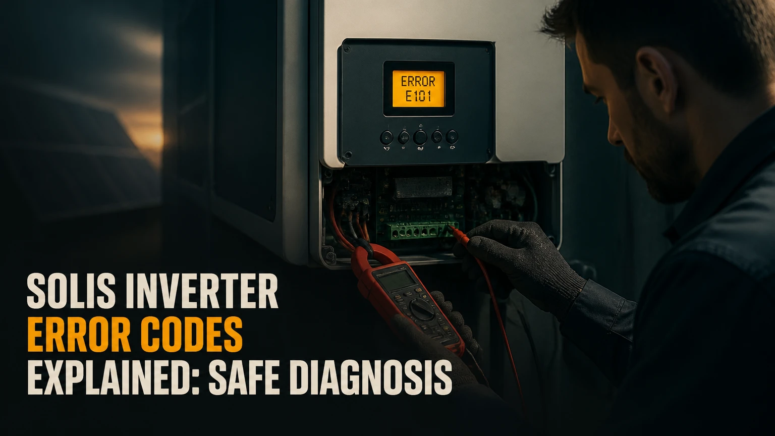
Solis inverter error codes are diagnostic alarms that identify abnormal grid, photovoltaic, temperature, communication, or internal hardware conditions. The code tells you where the inverter detected an unsafe value, but the correct repair depends on the exact Solis model, firmware, grid profile, installation, and whether the alarm is active or historical.
Key Facts
Solis code 1010, commonly labeled OV-G-V, indicates an over-grid-voltage condition on many models.
Solis code 1012, commonly labeled NO-GRID, means the inverter does not detect usable AC grid voltage.
PV ISO-PRO or code 1033 indicates that the photovoltaic array insulation reading is below the configured safety limit.
LimByEPM and LimByVg usually describe active power-limiting functions, not failed hardware.
Solis alarm numbers and labels vary by product family, firmware, country, and grid standard.
Repeated alarms require an installer or qualified electrician; opening the inverter or unplugging energized DC connectors is unsafe.
What Do Solis Inverter Error Codes Mean?
A Solis inverter error code is a firmware-generated diagnostic message tied to a measured electrical or operating condition. The inverter compares grid voltage, frequency, PV voltage, insulation resistance, temperature, current, relay state, and communications against configured limits, then disconnects or reduces output when protection requires it.
An alarm is not always proof that a component has failed. For example, NO-GRID can result from a real utility outage, a switched-off AC isolator, a tripped breaker, or an incorrectly wired installation. OV-G-V can indicate a high utility voltage, but it can also appear when voltage rises at the inverter because of excessive cable resistance during high export.
Solis documentation uses both text labels and numeric identifiers. The same family of condition may appear as a different number on another generation, so the display text, model number, firmware version, and event timestamp matter more than a number copied from a generic list.
How Does a Solis Inverter Create an Alarm?
The control processor samples electrical sensors and protection circuits, compares readings with the selected grid code, and commands contactors or relays to stop unsafe energy transfer. Solis inverter alarms can therefore protect the inverter, solar array, building wiring, utility network, and people working nearby.
A short event may clear automatically after the required reconnection delay. A persistent event remains active until the underlying condition disappears, while a historical event records that the condition occurred even if the inverter is now producing normally.
How Can You Retrieve the Active or Historical Code?
You can retrieve Solis alarm history from the inverter LCD or from SolisCloud. The LCD normally provides the most direct local record, while SolisCloud helps identify timing, repetition, and whether multiple inverters experienced the same event.
Method 1: Check the Solis LCD
- Press Enter to open the main menu.
- Select Advanced Info and press Enter.
- Enter the installer access code shown in the applicable Solis manual. Many units use 0010, but the access method is model-specific.
- Open Alarm Message, Alarm, or Error Info.
- Record the exact text, numeric code, date, time, and whether the event is active.
Many Solis units retain up to 100 alarm entries, but storage capacity depends on the product and firmware. Do not alter grid parameters while viewing the menu. A wrong grid profile can create non-compliant operation and may affect warranty support.
Method 2: Check SolisCloud
Open the SolisCloud app or web portal, select the plant, choose the inverter, and open Alarm, Events, or Logs. Export or photograph the event history when possible.
SolisCloud adds an important diagnostic dimension: time. An OV-G-V alarm that appears daily between 11:00 and 14:00 suggests a different investigation from one that appears during a utility outage at night. A communication alarm may indicate lost monitoring rather than lost solar production, so compare the portal record with the inverter’s local display.
Which Solis Alarm Category Does the Code Belong To?
Solis alarms generally fall into grid, PV or DC, internal hardware, temperature, communication, and operating-status groups. Categorizing the message first prevents an owner from treating a utility-voltage problem as a failed inverter.
| Category | Common label or code | What the inverter detected | First safe action |
|---|---|---|---|
| Grid voltage | OV-G-V, 1010 | AC voltage above the configured limit | Check whether the alarm repeats at high export; contact installer |
| Grid voltage | UN-G-V, 1011 | AC voltage below the configured limit | Check for local outage or heavy loads; arrange qualified testing |
| Grid presence | NO-GRID, 1012 | No acceptable AC grid detected | Check visible breaker and isolator position |
| Grid frequency | UN-G-F or OV-G-F | Frequency outside the selected range | Record time and grid profile; do not change limits casually |
| PV insulation | PV ISO-PRO, 1033, F02 | Low resistance between PV circuit and earth | Shut down according to the manual and call an installer |
| DC voltage | OV-DC, F01 | PV input voltage exceeds the inverter rating | Stop operation and have string design checked |
| Internal hardware | F05, IGBT, OV-BUS, UN-BUS | Relay, switching module, or DC bus abnormality | Preserve logs and request service |
| Temperature | OV-TEM, F04 | Internal temperature above its limit | Check airflow and ambient conditions without opening the unit |
What Does OV-G-V or Code 1010 Mean?
OV-G-V, commonly associated with code 1010 on many Solis products, means the inverter measured AC grid voltage above its configured operating range. Solis support materials describe separate 1010 variants on some products, so the complete display text and suffix should be recorded.
The local voltage may be within the utility’s service range at the main board but higher at the inverter terminals. A long, undersized, damaged, or loose AC cable can create voltage rise while the inverter exports power. The correct test compares voltage at the switchboard and inverter during the event, which requires qualified electrical equipment and access.
| Alarm | Common identifier | Typical pattern | Likely investigation |
|---|---|---|---|
| Over-grid voltage | OV-G-V | Midday, high solar export | AC cable voltage rise, utility voltage, export setting |
| Under-grid voltage | UN-G-V | Heavy site load or outage | Utility supply, loose connection, cable drop |
| No grid | NO-GRID | Immediate shutdown or after breaker trip | AC breaker, isolator, wiring, utility outage |
| Frequency low/high | UN-G-F, OV-G-F | Utility event or wrong profile | Grid frequency, country code, commissioning setup |
| Phase issue | G-PHASE or phase imbalance | Three-phase installation | Phase sequence, neutral, loose terminal, imbalance |
What Do UN-G-V, NO-GRID, and Frequency Alarms Mean?
UN-G-V, commonly code 1011, means detected grid voltage is below the configured lower limit. NO-GRID, commonly code 1012, means the inverter detects no acceptable AC supply, often because the AC isolator or breaker is open, the property has lost power, or a connection is defective.
UN-G-F and OV-G-F indicate frequency outside the selected operating window. The supplied overview gives typical 50 Hz limits near 49.5-50.5 Hz and 60 Hz limits near 59.3-60.5 Hz, but the actual limits depend on the approved regional grid standard. A wrong country profile can therefore create nuisance alarms, while changing the profile to suppress an alarm can violate interconnection rules.
A three-phase G-PHASE condition requires attention to phase sequence, phase voltage, neutral integrity, and balance. Do not assume that swapping conductors is a homeowner fix.
What Do PV and DC Solis Codes Indicate?
PV and DC alarms concern the solar array, string design, connectors, polarity, insulation, or the inverter’s DC input stage. These alarms can involve lethal DC voltage even when the AC breaker is off, because illuminated modules continue producing electricity.
What Does PV ISO-PRO or 1033 Mean?
PV ISO-PRO, commonly code 1033 and sometimes associated with F02, means the inverter’s insulation-monitoring circuit detected insufficient resistance between the PV conductors and earth. Water in a connector, crushed cable insulation, a damaged junction box, or a fault to a module frame can cause the reading.
The threshold is model-dependent. A 200 kΩ figure appears in some published Solis troubleshooting contexts, but users must not treat 200 kΩ as a universal Solis setting. Rain, condensation, washing, and morning dew can make an intermittent fault appear only in wet conditions.
A qualified installer can isolate strings and perform insulation testing with equipment suitable for the array. Do not lower an insulation threshold to force production. That action can conceal a dangerous earth fault.
What Do OV-DC, ARC-FAULT, and Reverse-DC Mean?
OV-DC or F01 indicates that PV open-circuit voltage may exceed the inverter’s permitted DC input range. Cold weather raises module voltage, so a string that appears acceptable on a warm design day may exceed the rating during the coldest expected conditions.
ARC-FAULT or F07 indicates that the inverter’s arc detection system identified an electrical signature associated with arcing. Loose terminals, incompatible connectors, damaged cable, and poor crimping are possible causes. Reverse-DC, commonly code 1028 on some lists, indicates reversed PV polarity at an input or string connection.
| DC condition | Common code | Typical trigger | Safe diagnostic boundary |
|---|---|---|---|
| PV insulation fault | 1033, F02 | Wet MC4 connector or damaged cable | Installer insulation test |
| DC overvoltage | F01 | Excessive cold-weather string Voc | Designer checks string calculation |
| Arc detection | F07 | Loose or damaged energized connection | Isolate and inspect by qualified person |
| Reverse polarity | 1028 | Positive and negative conductors swapped | Installer verifies polarity before reconnection |
| DC overcurrent | Model-dependent | String or input current beyond rating | Compare array design with inverter datasheet |
Which Messages Are Operating States, Not Failures?
LimByEPM and LimByVg usually indicate controlled output reduction rather than a failed Solis inverter. LimByEPM means an Export Power Manager or smart meter is limiting power to meet a configured export limit, while LimByVg indicates Volt-Watt or grid-voltage curtailment.
The distinction matters because replacing an inverter will not remove a correctly functioning export limit. LimByEPM may occur when site demand is low and the system is configured for zero export. LimByVg may appear during periods of elevated grid voltage, when the inverter reduces output to comply with the grid-support function.
| Display message | Meaning | Production effect | Useful check |
|---|---|---|---|
| LimByEPM | Export control is active | Output follows export limit | Meter communications and export setting |
| LimByVg | Voltage-based curtailment is active | Output falls as voltage rises | Grid voltage trend and AC cable rise |
| Waiting | Reconnection timer or startup state | No immediate export | Grid values and countdown |
| Normal | No active protective alarm | Available production | Compare output with irradiance |
| Meter failure | Export-control measurement unavailable | May limit or stop output | CT orientation, meter wiring, communications |
What Do Internal Faults Such as F05 and IGBT Mean?
Internal Solis faults indicate that the inverter detected abnormal behavior in components such as grid relays, insulated-gate bipolar transistors, DC bus capacitors, sensors, or control boards. These messages are service events, not invitations to remove the cover.
F05 commonly refers to a relay fault on some Solis families. IGBT-OV-I or related IGBT messages can indicate excessive current in the switching bridge, but a transient external condition can also trigger protection. OV-BUS and UN-BUS refer to abnormal DC-link bus voltage. F04 or OV-TEM indicates excessive internal temperature on models using that label.
| Internal alarm family | Component area | Typical symptom | Normal service route |
|---|---|---|---|
| Relay fault, F05 | AC contactors or relay feedback | Repeated startup failure | Installer and Solis service |
| IGBT overcurrent | Power switching bridge | Immediate shutdown under load | Warranty diagnosis |
| OV-BUS or UN-BUS | DC-link capacitors and sensing | Startup or load-related trip | Board-level service |
| OV-TEM or F04 | Heatsink, fan, thermal sensor | Hot-day derating or shutdown | Cooling inspection, then service |
| BMS-Lose | Battery communications | Hybrid battery unavailable | Approved battery protocol check |
The supplied overview suggests multimeter, diode-mode, and megohmmeter tests, but those tests belong to trained technicians following the relevant service procedure. A homeowner should provide logs, not perform live internal measurements.
How Do You Troubleshoot a Solis Alarm Safely?
Safe troubleshooting starts with evidence collection, visible checks, and model-specific shutdown instructions. A simple restart may clear a transient event, but it cannot repair damaged wiring, high utility voltage, low insulation resistance, or failed power electronics.
Before You Touch the System
Record the inverter model, serial number, firmware version, exact alarm text, timestamp, weather, production level, and whether the message is active. Check the user manual for the correct isolation order because hybrid, battery, and retrofit systems may have additional switches.
Do not open the inverter, remove covers, loosen terminals, test energized DC connectors, or disconnect MC4 connectors under load. Solis inverters and PV strings can retain hazardous voltage after shutdown.
Step 1: Check Visible External Conditions
Look only at equipment intended for user operation. Confirm whether the property has power, whether a clearly labeled AC breaker or isolator is visibly in its normal position, and whether the inverter shows a screen or indicator light.
Do not repeatedly reset a breaker that trips. Stop if you see scorching, melted plastic, water inside equipment, smoke, an unusual smell, or exposed conductors.
Step 2: Capture the Alarm History
Photograph the display and save the SolisCloud event record. Note whether the code appears once, follows rainfall, begins after installation, or returns at a consistent generation peak.
A single historical alarm that does not recur has a different priority from an active PV insulation fault or repeated internal fault. Pattern is diagnostic evidence.
Step 3: Perform Only the Approved Restart
If the manual permits a user restart and no damage is visible, switch the system off using the labeled external controls and wait the specified discharge period. Some general Solis procedures use AC off, DC off, a waiting period of about 5-10 minutes, then AC on followed by DC on, but the model manual takes priority.
The inverter should complete its startup checks and reconnect only after the grid conditions satisfy the required delay. If the same alarm returns, stop cycling and escalate.
Step 4: Match the Code to the Correct Specialist
Grid voltage, frequency, phase, cable, and breaker issues require a licensed electrician or installer. PV insulation, polarity, arc, and string-voltage faults require a solar installer with suitable DC and insulation-testing equipment. Internal and battery faults should go through the installer and Solis technical support.
| Condition | First contact | Typical owner action | Escalation trigger |
|---|---|---|---|
| NO-GRID after local outage | Utility or electrician | Check visible supply switch | Alarm remains after power returns |
| OV-G-V each afternoon | Installer and electrician | Save time-stamped logs | Voltage rises during export |
| PV ISO-PRO after rain | Solar installer | Stop repeated resets | Alarm remains when dry |
| F05 or IGBT fault | Installer and Solis | Preserve photos and serial | Code returns after restart |
| LimByEPM | Installer or system designer | Check portal output limit | Meter data conflicts with site use |
Why Do Solis Alarms Keep Returning?
Recurring Solis alarms usually follow a repeatable external condition, not random firmware behavior. The time, weather, output level, and electrical state at each event reveal whether the likely source is grid, array, temperature, export control, or hardware.
An OV-G-V alarm at the same afternoon production peak points toward voltage rise or utility voltage. A PV ISO-PRO alarm after rain points toward moisture or insulation breakdown. A temperature alarm during hot, dusty weather points toward restricted clearance, failed cooling, high ambient temperature, or an internal sensor issue.
New installations deserve a separate interpretation. Incorrect string polarity, an unsuitable grid profile, an unconfigured export meter, or a loose termination can appear immediately after commissioning. Systems that worked for years may instead develop connector moisture, cable damage, fan wear, relay wear, or changing utility voltage.
How Much Do Solis Repairs Cost and How Long Do They Take?
Typical service costs range from approximately BDT 500-1,500 for minor DC connector materials to BDT 65,000-180,000 for a complete out-of-warranty inverter replacement. These are indicative Bangladesh-market figures from the supplied context, not Solis fixed prices; travel, inverter capacity, access, import costs, warranty status, and installer rates change the final invoice.
| Repair pathway | Typical part cost | Typical labor cost | Typical downtime |
|---|---|---|---|
| MC4 repair or re-crimping | BDT 500-1,500 | BDT 2,500-5,000 | 1-3 hours |
| AC cable or breaker correction | BDT 5,000-15,000 | BDT 4,000-8,000 | 1-2 days |
| Relay or control-board replacement | BDT 25,000-45,000 | BDT 6,000-12,000 | 5-10 days |
| Full inverter replacement | BDT 65,000-180,000 | BDT 10,000-20,000 | 3-7 days |
Warranty coverage may reduce hardware cost, but approval normally requires the model, serial number, installation date, alarm history, photographs, and installer diagnosis. A warranty claim is stronger when the owner has not changed grid settings or opened the enclosure.
Should You Change the Grid Profile or Replace the Inverter?
Changing a grid profile is appropriate only when a qualified commissioning professional confirms that the selected profile does not match the approved local standard. It is not an acceptable workaround for persistent OV-G-V, UN-G-F, or OV-G-F alarms.
Physical electrical correction is preferable when voltage rise, phase wiring, cable capacity, or loose terminations cause the event. Manufacturer repair is preferable for persistent F05, IGBT, bus, or sensor faults, especially during the warranty period. Replacement makes economic sense when repair cost, age, capacity, parts availability, and downtime outweigh a new unit.
| Resolution route | Best use case | Typical time | Main risk |
|---|---|---|---|
| Correct grid profile | Verified commissioning mismatch | 30-90 minutes | Non-compliant settings |
| Repair AC or DC installation | Cable, connector, breaker, or wiring fault | 1-2 days | Requires isolation and testing |
| Solis warranty service | Repeated internal hardware alarm | 5-10 days | Support and shipping delay |
| Replace inverter | Uneconomic or unavailable repair | 3-7 days | New configuration cost |
What Troubleshooting Mistakes Should You Avoid?
The most dangerous Solis troubleshooting mistakes involve defeating protection or interrupting live DC. Owners should never reduce an insulation-resistance limit to suppress PV ISO-PRO, hot-unplug MC4 connectors while generating, or connect an unapproved battery to clear BMS communications alarms.
Three practitioner rules prevent many secondary failures:
- Treat recurrence as evidence. A code that returns at the same time or weather condition deserves trend analysis, not repeated resets.
- Compare locations, not assumptions. OV-G-V diagnosis requires voltage measurements at relevant points during export, because the inverter terminal voltage may differ from the service entrance.
- Preserve the original configuration. Record settings before any authorized change, and never use a neighboring model’s manual as a substitute for the installed unit’s documentation.
Solis inverter alarms are also poor tools for estimating energy yield. A LimByEPM event may be entirely correct under a zero-export design, while a communication loss may leave the inverter producing normally even though the portal looks offline.
When Should You Call Solis Support?
Contact the installer first when the system is under workmanship warranty, newly commissioned, or connected to batteries, meters, or export controls. Contact Solis support through the applicable regional service channel when the installer confirms an internal fault, warranty replacement, firmware issue, or unresolved model-specific alarm.
Prepare the serial number, exact model, firmware version, alarm screenshots, SolisCloud history, installation date, grid country, weather pattern, and results of any qualified tests. Support can resolve cases faster when the event code is paired with a timestamp and operating condition rather than supplied alone.
What Is the Honest Limitation of Generic Code Lists?
Generic Solis code lists are useful for orientation, but they are not service manuals. Code meanings, numeric mappings, menu names, thresholds, reset behavior, and battery messages can differ among single-phase, three-phase, hybrid, commercial, and older inverter families.
A generic list cannot identify a failed connector without testing, distinguish utility voltage from cable voltage rise without measurements, or establish warranty eligibility from a code alone. Use the list to decide what evidence to collect and whom to call, not to authorize unsafe repair.
Frequently Asked Questions
Can a Solis inverter reset itself after an alarm?
A Solis inverter may clear a temporary grid alarm after measured voltage or frequency returns to the permitted range and the reconnection delay expires. A self-clearing event remains important if it repeats, because intermittent cable, utility, insulation, temperature, or relay problems can worsen without leaving a continuously active code.
Why is my Solis inverter producing less power without an error?
Reduced output can result from LimByEPM export control, LimByVg Volt-Watt response, battery charging limits, high module temperature, shading, clipping, or irradiance changes. Compare inverter power, grid voltage, export-meter data, battery state of charge, and SolisCloud status before treating lower production as hardware failure.
Is code 1010 always caused by the electricity company?
No. OV-G-V or code 1010 can result from utility voltage, but voltage rise between the supply point and inverter is also common in high-export installations. A qualified electrician should measure the relevant AC points during the alarm and inspect conductor size, cable length, terminations, and phase loading.
Can rain cause a PV ISO-PRO alarm?
Rain can expose an existing insulation weakness in a PV string. Moisture may enter a connector, damaged cable, junction box, or rooftop conduit, lowering resistance between a conductor and earth. A solar installer should isolate strings and perform the prescribed insulation tests instead of repeatedly restarting the inverter.
How long should I wait before restarting a Solis inverter?
Use the shutdown and restart timing in the exact Solis manual for the installed model. General procedures often include a 5-10 minute waiting period after external AC and DC isolation, but hybrid systems and battery arrangements can require additional steps. Never restart equipment showing smoke, heat damage, water ingress, or exposed wiring.
Do Solis hybrid inverters use the same codes as grid-tied models?
No. Hybrid Solis inverters can add battery-management, backup-output, state-of-charge, and communications alarms that do not appear on standard grid-tied models. The inverter model, battery model, BMS protocol, firmware, and wiring diagram must be checked together before interpreting a hybrid alarm.
The Bottom Line
Solis inverter error codes explained correctly require more than a number-to-definition list. Read the exact display message, identify the grid, PV, operating-status, temperature, communication, or internal category, record when the event occurs, and follow the model manual’s safe isolation procedure.
NO-GRID and visible breaker issues may begin with a simple external check. PV ISO-PRO, arc, overvoltage, phase, relay, IGBT, bus, and repeated grid alarms need qualified diagnosis. LimByEPM and LimByVg usually indicate controlled curtailment rather than failed equipment. The safest solution is the one that corrects the measured cause without bypassing Solis protection.